

The challenges of industrial hydraulic fracturing
PDF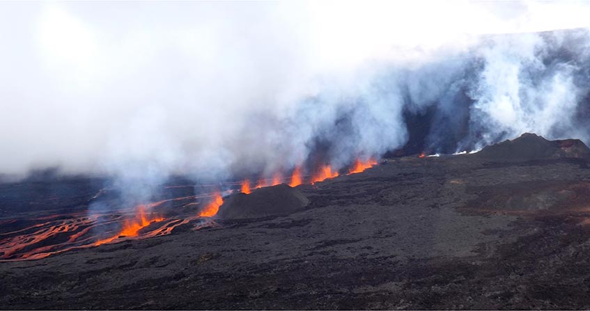
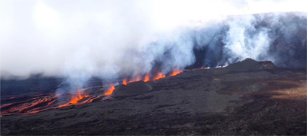
Hydraulic fracturing is a failure process that occurs when the pressure applied to the fluid contained in a rock exceeds a certain threshold. This process can occur naturally, as for example during basaltic volcanic eruptions (Figure 1), or artificially, as for example during hydrocarbon production. Until recently, hydrocarbon production involved only natural reservoirs and the practice of hydraulic fracturing required for this operation did not pose any environmental difficulties. But for the past fifteen years or so, this technique has been applied to the exploitation of hydrocarbons within their mother rock. This application now requires better control of the geometry of hydraulic fractures to avoid any negative impact on the environment. This control is ensured by real-time monitoring of the microseismicity induced by these fluid injections, which requires special equipment given the weakness of the signals involved.
1. Hydraulic fracturing: a natural phenomenon
All rocks have a certain porosity, i.e. a volume not filled with solids. This porous space can be filled with liquids (water, brines, hydrocarbons, lava,…), or gas (air, natural gas, etc…), very often under pressure. The solid part of the rock, on the other hand, transmits the natural stress that exist in any rocky massif, if only because of the weight of the land.
A hydraulic fracture is a pure tensile failure (see focus Basic concepts of fracture mechanics) that develops in a plane whose orientation depends on the stress characteristics.
The notion of stress is discussed further in the paper How matter deforms: fluids and solids under the heading Physics of this encyclopedia. Let us recall here a major difference between pressure and stress that allows a better understanding of the development of hydraulic fractures.
When pressure is applied to a flat surface, a force is applied perpendicular to the surface, the amplitude of which is proportional to the value of the pressure and the area of the surface. When a stress is applied to the same surface, the result is a force whose direction is generally not perpendicular to that surface. This force can be decomposed into a component perpendicular to the surface, called a normal component, and a component within the plane of the surface, called a shear component. For all stress fields, there exists it is shown that the amplitudes of these two components depend on the orientation of the surface considered. There are three surface orientations, perpendicular to each other, for which the shear components are zero. The amplitude of the normal component associated with each of these three surface orientations varies with the orientation of the surface. The smallest is called the minimum principal component and the largest maximum principal component.
In summary, it can be said that a fluid at rest transmits pressure in the same way in all directions, which is not the case with a solid at rest. As a result, hydraulic fractures develop in the plane perpendicular to the direction of the minimum principal component of stress in the solid.
The rate of propagation of a hydraulic fracture depends on the distribution of fluid pressure in the fracture. When the fracturing fluid is an incompressible liquid (water, mud, lava, etc…), the propagation process is stable, because as soon as the rupture begins, the volume of the fracture increases, causing the pressure in the fluid to drop. To propagate the fracture, liquid must be injected and therefore the rate of propagation depends on the injection rate in the fracture. As soon as the injection stops, the fracture stops.
For example, the propagation rate of a volcanic dyke (Figure 1) during its formation is comparable to that of a walking man (about 100 m/min.).
The control of the geometry of artificial hydraulic fractures therefore requires an a priori knowledge of the variations of the minimum principal stress in the massif.
2. Application of hydraulic fracturing to hydrocarbon exploitation
Hydrocarbons come from the decomposition of organic matter that settles to the ocean floor at the same time as the various elements that will form sedimentary rocks (sandstone, limestone, clay, salts, etc…). When these sedimentary materials are buried deep underground, hydrocarbons tend to migrate to the most porous areas of sandstone and limestone. A distinction is therefore made between mother rocks, where hydrocarbons are generated, and reservoir rocks, where hydrocarbons are stored on geological time scales.
Conventional hydrocarbon exploitation involves drilling (see focus Some characteristics of drilling techniques) that will reach the reservoir rocks. Drilling allows the hydrocarbons to flow to the surface. This flow causes the pressure in the vicinity of the borehole to drop rapidly and thus the flow rate at the drill head decreases.
As early as the 1940s, it was realized that it was possible to maintain production at a satisfactory level by making hydraulic fractures. A pressurized liquid is injected into the reservoir rock, creating a tensile failure that is stable and perpendicular to the minimum principal stress in the solid mass [1].
Operators have thus developed products whose characteristics vary with time: high viscosity when injecting sand, low viscosity 24 to 48 hours after their installation in the field to allow hydrocarbon production.
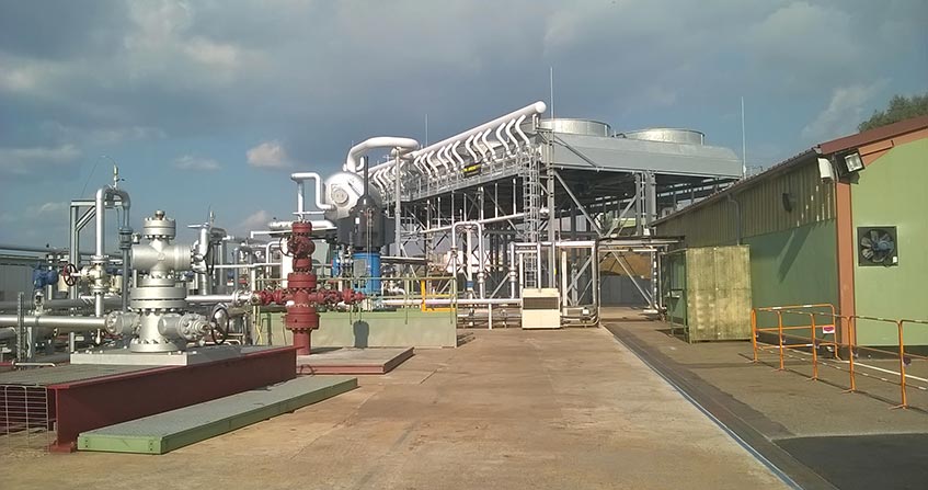
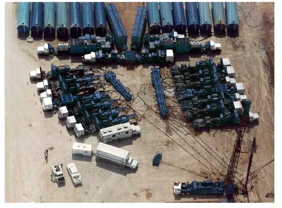
The volumes injected are generally a few hundred cubic metres (Figure 3) and exceptionally reach a few thousand cubic metres. For calcareous reservoir rocks, which can dissolve in acids, acid fluids are used for fracturing which will locally dissolve the rock, creating flow channels in the walls of the hydraulic fracture. Thus, at the end of the injection, the fracture will remain permeable when closed, without the need for sand injection. In oil jargon, these operations are referred to as “acid-frac“.
Experience has shown that, at equal depth, the minimum principal stress is lower in sandstones and limestones than in marls and clays, which are also very low permeable. Thus, the marl and clay banks that ensure the existence of hydrocarbon reservoirs also constitute a barrier to the vertical extension of hydraulic fractures produced for exploitation.
Today, all hydrocarbon production (in gaseous or liquid phases) carried out in the world today involves hydraulic fracturing operations, and this has been the case since the 1940s, without any inconvenience for the populations living on the surface. It should be noted that hydraulic fracturing is only one of the “tools” used to optimize the exploitation of reservoir rocks. One of the other traditional “tools” consists in optimizing the location of development wells and using certain wells for the injection of more or less hot fluids that “push” the hydrocarbons in place to the production areas. The heat of the injected fluids makes it possible to raise the temperature locally and thus reduce the viscosity of the hydrocarbons in place, which favours their flow. In practice, it is considered that the optimal use of a reservoir leaves between 35% and 45% of the total amount of hydrocarbon it contains in place.
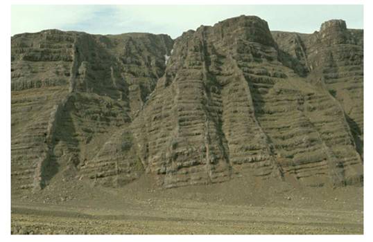
Since we know how to drill horizontally (see focus Some characteristics of drilling techniques), we know how to exploit hydrocarbons that have not migrated from their mother rock, and that are called unconventional reservoirs or, through abuse of language, shale gas. These hydrocarbons, often gases, are still in their mother rock because it is porous but impermeable (the pores are insulated and do not communicate with each other). Horizontal drilling is carried out in the bedrock and involves numerous hydraulic fracturing operations (Figure 4). But while the fluids produced naturally include the desired hydrocarbons, often in the gas phase, they also contain very abundant brines which must be reinjected at depth. They are the real source of the potential pollution caused by these operations, including induced seismicity (see discussion below).
In addition, the minimum principal stress in source rocks is generally higher than that existing in the terrain above and below these source rocks. Thus, if the volumes injected during hydraulic fracturing operations are too large, there is a risk that these hydraulic fractures will connect the source rock with the more permeable soils above. For operations that are too superficial (less than 500 m deep), there is a risk of pollution of the groundwater table used for current consumption. The important thing is therefore to have, in real time, tools to control the vertical extension of hydraulic fractures in order to eliminate these risks of pollution. This tool exists, it is induced microseismicity.
3. Micro-seismicity induced by pressurized fluid injections
The injection of fluids under pressure into a rock mass can, depending on the amplitude of the pressure disturbance, either induce slippages on pre-existing fractures or generate a hydraulic fracture [2]. Indeed, the pressure of the fluid contained in a pre-existing fracture is opposed to the normal component of the stress supported by this fracture, but leaves the shear component unchanged. It can be seen that when the difference between the pressure of the fluid in a fracture and the normal component supported by the fracture becomes too small, the shear component induces a tangential displacement in the plane of the fracture.
Thus, depending on the injection rates and whether or not there are pre-existing fractures in the injection well, there may be either a hydraulic fracture or a slip along pre-existing fractures. We have seen that the propagation of a hydraulic fracture is stable and therefore does not generate microseismic events. But the slippages induced on pre-existing fractures are often unstable and generate microseismicity.
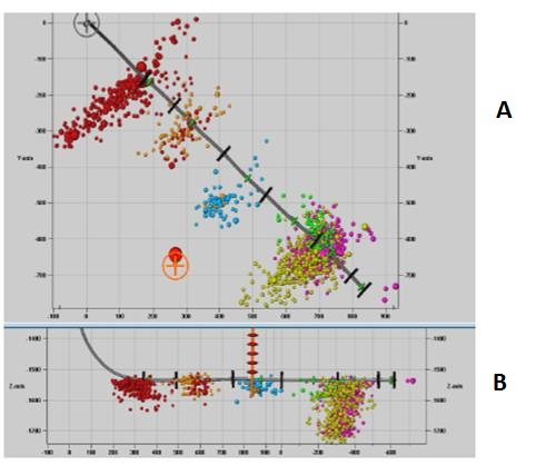
Horizontal drilling is carried out that remains in the bedrock. Then a series of small hydraulic fractures are made, which must also remain contained in the mother rock. The extension of these fractures is monitored in real time by mapping the induced micro-seismic activity. The detection of these microseisms requires the installation of very special listening equipment, due to the high frequencies of the transmitted signals and the low amplitude of these signals.
Seismological work carried out over the past forty years has shown that the amplitude of unstable shear movements, and therefore the generator of micro-seismic signals, depends in particular on the dimensions of the sliding surface and the magnitude of the fall in the shear component released by the failure. Microseismic earthquakes, like earthquakes, are characterized by their magnitude. The magnitudes scale is logarithmic (and therefore non-linear). Thus, to set orders of magnitude, a magnitude 4 corresponds to a dynamic failure on a fault about 1 km long, while a magnitude 3 corresponds to a dynamic failure length of 300 m and a magnitude 5 to a dynamic failure length of 3 km. Microseismicity is generally referred to as microseismicity for events of magnitude less than 3. For naturally seismic regions, such as California, at least one magnitude 4 is recorded per week and buildings are dimensionned accordingly.
It should be noted that the important parameter for the disturbance effect of seismic movements is not so much the magnitude as the value of the acceleration and the duration during which this acceleration is felt. These characteristics depend on the distance between the source of the rupture and the point where the effect is considered. The greater the distance, the more the signal is attenuated. Thus a magnitude 4 10 km deep may be less disturbing at the surface than a magnitude fracture 3 3 km deep. But these effects do not only depend on distance, they also involve the nature of the terrain traversed by the seismic wave and that are known as site effects, which depend on geological and geotechnical structures at the observation point. The magnitude of micro-seismic events induced by hydraulic fractures is generally much smaller than 2, it is even often negative (metric or even decimetric dimension of the source).
We will remember that one of the real problems associated with the exploitation of shale gas is not the microseismicity associated with hydraulic fractures, but the seismicity induced by the reinjection of large quantities of brine produced as a result of exploitation (magnitudes greater than 4). These brines must be reinjected at depth and are at the origin of disruptive earthquakes, some of which have reached magnitudes greater than 5 in Oklahoma, United States. These earthquakes could probably have been avoided if the injection rates, and therefore the overpressure associated with these injections, had been better controlled.
References and notes
[1] Hubbert M.K. & Willis D.G., 1957. Mechanics of hydraulic fracturing. Trans., Am. Inst. Min. Eng. 210, pp 153-163.
[2] Cornet F.H., 2016. Seismic and aseismic motions generated by fluid injections. Geomech. Ener. Envir., vol. 5, pp 42-54.
The Encyclopedia of the Environment by the Association des Encyclopédies de l'Environnement et de l'Énergie (www.a3e.fr), contractually linked to the University of Grenoble Alpes and Grenoble INP, and sponsored by the French Academy of Sciences.
To cite this article: CORNET François Henri (January 5, 2025), The challenges of industrial hydraulic fracturing, Encyclopedia of the Environment, Accessed July 29, 2026 [online ISSN 2555-0950] url : https://www.encyclopedie-environnement.org/en/soil/the-challenges-of-industrial-hydraulic-fracturing-2/.
The articles in the Encyclopedia of the Environment are made available under the terms of the Creative Commons BY-NC-SA license, which authorizes reproduction subject to: citing the source, not making commercial use of them, sharing identical initial conditions, reproducing at each reuse or distribution the mention of this Creative Commons BY-NC-SA license.