工业水力压裂的挑战

Encyclopedie environnement - fracturation hydraulique - natural hydraulic fracture

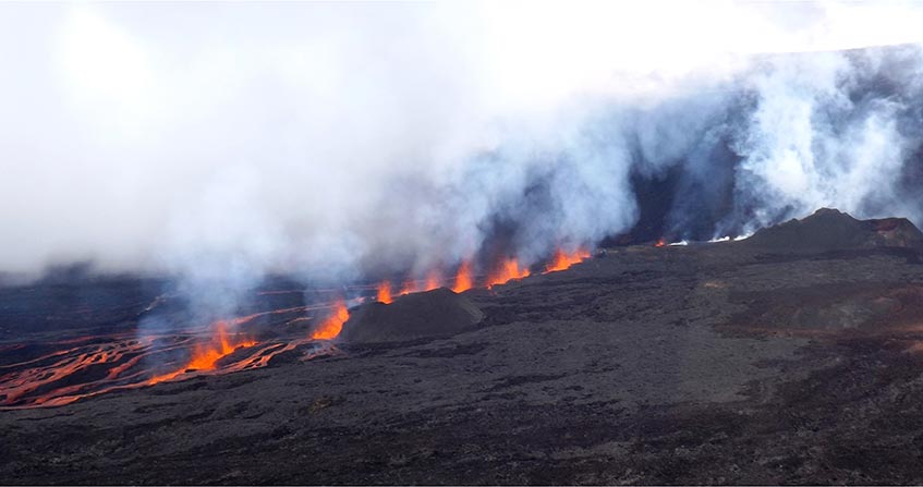
  水力压裂是指施加于岩石中流体的压力超过一定阈值时发生的破裂过程。这一过程可以是自然发生的,例如玄武岩火山爆发(图 1),也可以是人为的,例如油气开采。直到最近,油气开采只涉及到自然储层,水力压裂作业并未造成任何环境问题。但在过去的15年里,这项技术一直被应用于母岩内部的油气的开采。此应用现在需要更好地控制水力裂缝的几何形状,以避免对环境造成任何负面影响。这种控制是通过实时监测这些流体注入引起的微震活动来确保的,鉴于所涉及的信号较弱,则需要特殊设备来检测。

1.水力压裂:一种自然现象

  所有的岩石都有一定的孔隙,即未填充固体的体积。在通常的压力下,这种多孔空间可以充满液体(如水、卤水、烃类化合物、熔岩等)或气体(如空气、天然气等)。另一方面,即使仅仅是由于土地的重量,岩石的固体部分仍可以传递存在于任何岩石地块中的自然应力。

  水力裂缝是纯拉伸断裂(参见“断裂力学的基本概念”),其方向取决于应力特性。

  在这本百科全书物理学的主题下的《物质如何形变:流体和固体》一文中,进一步讨论了应力的概念。在此让我们回顾一下压力和应力的一个主要差异,这会有助于更好地理解水力裂缝的发展。

  当压力作用于平面时,将产生一个垂直于此表面的作用力,其大小与压力值和表面面积成正比。当对同一表面施加一种应力时,会产生一个力,其方向通常与该表面不垂直。这种力可以分解为垂直于表面的分量(称为法向分量)和表面平面上的分量(称为切向分量)。对于所有应力场,这两个分量的振幅取都决于所考虑的表面方向。有三个相互垂直的表面分量,切向分量为零。与这三个方向均有关的法向分量的振幅随表面方向变化而变化。其中,最小的被称为最小主成分,最大的被称为最大主成分。

  总之,静止的流体可以说是以同样的方式向各个方向传递压力,而静止的固体则不是这样。因此,水力裂缝在垂直于固体中最小主应力分量方向的平面上形成。

环境百科全书-土壤-富尔奈斯火山
图1.自然水力压裂的一个例子:富尔奈斯火山(留尼汪岛)玄武岩喷发的第一阶段。[来源: Aline Peletier 拍摄(OVPF/IPGP)]

  在留尼汪岛熔炉峰所观察到的玄武岩火山的喷发,这是自然界水力压裂的一个例子。在火山下面几公里处有一个岩浆室,充满了熔融岩石(岩浆)。当腔室中的压力达到某个临界值时,会形成水力裂缝,使熔岩逸出到表面(图 1)。当熔岩喷发停止、岩浆凝固时,这些裂缝形成的结构被称为火山岩脉。

  水力裂缝的扩展速率取决于裂缝内流体压力的分布。当压裂液是不可压缩的液体(水、泥浆、熔岩等)时,扩展过程是稳定的。因为随着裂缝开始,裂缝体积增加,这就会导致流体中的压力降低。裂缝的扩展需要注入液体,因此扩展速率取决于裂缝的注入速率。注入一旦停止,裂缝的扩展就会停止。

  例如,一个火山岩脉(图 1)形成过程中,其扩展速率与人步行的速率大致相当(每分钟约 100 )。

环境百科全书-土壤-冰岛的岩墙
图2.冰岛的岩墙:一旦岩浆冷却,火山岩墙对应于大型平面结构,其几何结构证明了岩浆侵位时局部主应力的方向。[来源:A.Gudmunsson 照片]。

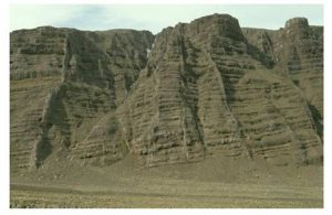
  由于水力裂缝的扩展垂直于岩体中的最小主应力,其比大尺度的几何结构受到最小主应力变化的调控。例如,图 2 显示,一旦岩浆冷却,火山岩脉对应于大型扁平的结构会提供局部应力状态信息。

  因此,控制人工水力裂缝的几何结构需要提前了解岩体中最小主应力的变化。
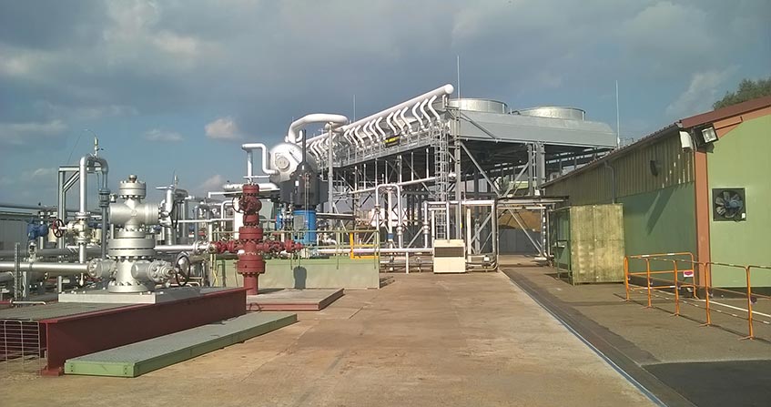
2.水力压裂在油气开发中的应用

  与形成沉积岩的各种元素(砂岩、石灰石、粘土、盐等)同时沉积在海底的有机物分解时,这就产生了油气。当这些沉积物质被深埋时,油气往往会迁移到砂岩和石灰岩中最多孔的区域。因此,在生成油气的母岩和在地质时间尺度上储存油气的储集岩之间得以区分。

  传统的油气开采是通过钻井(参见焦点“钻井技术的一些特征”)到达储集岩。钻井可以使得油气向表面流动。这种流动导致钻孔附近的压力迅速下降,而钻头处的流速也因此降低。

  早在 20 世纪 40 年代,人们就认识到,通过水力压裂可以将产量维持在很好的水平。将加压液体注入储集岩,产生稳定的拉伸破坏,并垂直于固体块中的最小主应力[1] 。

  但如果我们只注水,当注水停止时,下降的压力和闭合的裂缝对油气开采无任何影响。在实际操作中,该技术是用标准液体(钻井泥浆或水)开始压裂,然后注入粘性液体,将砂悬浮其中(图 3)(参见本百科全书中的“沙子”一节)(链接:沙子)。在当其注入结束时,压力下降且裂缝闭合,砂粒保持在原位,从而确保有效地油气开采。该操作由一些专业操作员进行,他们已学会控制用于悬砂液体的粘度。事实上,该粘度必须很高,以便悬浮液中砂的密度尽可能高,但压裂作业结束之时必须尽可能低,以免阻碍油气开采。

环境百科全书-土壤-非常规油气开采的水力压裂作业
图3.非常规油气开采的水力压裂作业。底部有可供注入约 500 立方米的水箱。在右下角的图中可以看到钻头。储罐前面的卡车准备流体-砂混合物,流体-砂混合物由两排卡车安装的泵注入。每台泵的功率约为 500 马力。[来源:斯伦贝谢的照片]

  因此,操作员开发产品的特点是随时间而变化:注砂应粘度高,而现场安装24-48 小时后粘度低,以便油气开采。

  注入量通常为几百立方米(图 3),特殊情况时会达到几千立方米。对于可以用酸溶解钙质储集岩,使用酸液进行压裂,能将局部岩石溶解,从而在水力压裂壁中形成流动通道。因此,在注入结束时,裂缝闭合时仍保持渗透性,无需注砂。在石油术语中,这些操作被称为“酸压裂”。

  经验表明,在同等深度下,砂岩和石灰岩的最小主应力要低于同样渗透性很低的泥灰岩和粘土中。因此,泥灰岩和粘土层既确保了油气储藏的存在,也阻碍了开采产生的水力裂缝的垂直延伸。

  现今,世界上所有的油气生产(无论是气相还是液相)都涉及水力压裂作业, 自 20 世纪 40 年代以来一直如此,并未对生活在地面的居民造成过任何不便。值得注意的是,水力压裂只是优化储层岩开采的“工具”之一。另一个传统的“工具”——包括优化开发井的位置,并使用某些井注入或多或少热流体,将油气“推”到生产区。注入流体的热量使局部温度升高,从而降低油气的粘度,以利于其流动。在实际操作中,储层的最佳运行被认为是使其所含油气总量保持在 35%到 45%之间。

  既然我们已知道如何水平钻井(参见焦点“钻井技术的一些特征”),我们也知道如何开采未从母岩释放的油气,那些油气被称为非常规油气,或者因为滥用语言,称为页岩气。由于母岩是多孔而不渗透的(这些孔隙是绝缘的,彼此之间不连通),这些油气通常是以气体形式存在于母岩之中。水平钻井在基岩中进行,涉及大量水力压裂作业(图 4)。尽管这些自然液体包含所需的油气(通常为气相),但由于它们含有非常丰富的卤水,这些卤水必须回注到深处。它们是这些作业造成潜在污染的真正来源,包括诱发地震(见下文讨论)。

  此外,母岩中的最小主应力通常高于母岩上下地段中的主应力。因此,如果水力压裂作业的注入量过大,这些水力裂缝有可能将母岩与上方更具渗透性的土壤连接起来。在这种情况下,如果作业太浅(深度小于 500 ),则可能会对目前使用的地下水造成污染。因此,重要的是要有办法实时控制水力裂缝的垂直延伸,以消除这些污染风险。这个办法有,就是诱发微地震。

3.加压流体注入引起的微地震

  取决于压力扰动的幅度,受压流体注入岩石层,这可能会引起之前已存在裂缝的滑动或产生水力裂缝[2] 。事实上,已存在的裂缝中包含的流体压力与该裂缝支撑应力的法向分量相反,但切向分量会保持不变。可以看出,当裂缝中的流体压力与裂缝支撑的法向分量之间的差值变得过小时,切向分量会在裂缝平面内引起切向位移。

  因此,取决于注入速率和注入井中是否存在已有的裂缝,这可能会导致水力裂缝或沿已预先存在的裂缝滑动。我们已经看到,水力裂缝的扩展是稳定的,因此不会产生微地震。但在已有的裂缝上诱发的滑动通常是不稳定的,这会产生微地震。

环境百科全书-土壤-诱发微地震活动的位置有助于水力裂缝的延伸图的绘制
图4.确定诱发微地震活动的位置有助于绘制水力裂缝的延伸图(A)俯视图;裂缝垂直于钻孔。
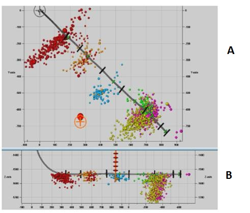
(B)显示水平钻孔几何形状和微地震传感器位置的垂直平面中的横截面图(垂直橙色结构)。
[图的来源:S.Maxwell,Sclumberger]。

  在其扩展过程中,水力裂缝总是在某个时刻与先前存在的渗透性或强或弱的裂缝相交。然后,水力裂缝中的流体可以将压力传递给这些裂缝中存在的流体。如果这些压力变化足够大,则可能引发失稳滑动。因此,可以通过定位与水力裂缝相交的既有裂缝上产生的微地震事件来绘制水力裂缝的延伸情况(图 4)。这是页岩气开采中使用的技术。

  在基岩剩余部分中进行水平钻孔。然后形成了一系列小型水力裂缝,这些裂缝也必须保留在母岩中。通过绘制诱发微震活动图,实时监测这些裂缝的扩展延伸。由于其发射的信号频率高、振幅低,所以检测这些微地震需要安装非常特殊的监听设备。

  过去四十年开展的地震学工作表明:不稳定剪切运动的振幅及由此产生的微震信号,尤其要取决于滑动面的尺寸和由破坏释放切向分量的下降幅度。微震地震和地震一样,以其震级为特征。震级是以对数来量化(因此是非线性的)。所以,为了设定数量级,3 级、4 级和 5 级分别对应于约 0.3公里、1公里 和 3公里 长的断层动态故障。微震通常指震级小于 3 级的微震事件。对于自然地震区,如加利福尼亚州,每周至少记录到一次4级地震,并相应地确定当地建筑物的尺寸。

  应注意的是,地震运动干扰效应的重要参数与其说是震级,不如说是加速度值和感知到该加速度的持续时间。这些特征取决于破裂源和考虑效应点之间的距离。距离越远,信号衰减越大。因此,4 级 10 公里深断裂的地表扰动可能比 3公里深的 3 级断裂小。但这些影响不仅取决于距离,还涉及到地震波穿过地形的性质。此性质被称为场地影响,而这取决于观测点的地质和岩土结构。水力裂缝引起微震事件的震级通常远小于 2 级,甚至常为负值(震源的米制或分米制范围)。

  因此,我们要记住的是,页岩气开采的真正问题之一不是与水力压裂有关的微地震,而是由于开采(大于 4 级)过程中产生的大量卤水的回注而引起的地震活动。这些卤水需要深层回注,但会引发破坏性地震,其中一些地震在美国俄克拉荷马州达到了 5 级以上。倘若注入速率及与这些注入相关的超压得到更好的控制,这些地震可能会避免的。


参考资料和说明
[1]  Hubbert M.K. & Willis D.G., 1957. Mechanics of hydraulic fracturing. Trans., Am. Inst. Min. Eng. 210, pp 153-163.

[2]  Cornet F.H., 2016. Seismic and aseismic motions generated by fluid injections. Geomech. Ener. Envir., vol. 5, pp 42-54.


环境百科全书由环境和能源百科全书协会出版 (www.a3e.fr),该协会与格勒诺布尔阿尔卑斯大学和格勒诺布尔INP有合同关系,并由法国科学院赞助。

引用这篇文章: CORNET François Henri (2024年3月8日), 工业水力压裂的挑战, 环境百科全书,咨询于 2024年7月27日 [在线ISSN 2555-0950]网址: https://www.encyclopedie-environnement.org/zh/sol-zh/the-challenges-of-industrial-hydraulic-fracturing/.

环境百科全书中的文章是根据知识共享BY-NC-SA许可条款提供的,该许可授权复制的条件是:引用来源,不作商业使用,共享相同的初始条件,并且在每次重复使用或分发时复制知识共享BY-NC-SA许可声明。

The challenges of industrial hydraulic fracturing

Encyclopedie environnement - fracturation hydraulique - natural hydraulic fracture

Hydraulic fracturing is a failure process that occurs when the pressure applied to the fluid contained in a rock exceeds a certain threshold. This process can occur naturally, as for example during basaltic volcanic eruptions (Figure 1), or artificially, as for example during hydrocarbon production. Until recently, hydrocarbon production involved only natural reservoirs and the practice of hydraulic fracturing required for this operation did not pose any environmental difficulties. But for the past fifteen years or so, this technique has been applied to the exploitation of hydrocarbons within their mother rock. This application now requires better control of the geometry of hydraulic fractures to avoid any negative impact on the environment. This control is ensured by real-time monitoring of the microseismicity induced by these fluid injections, which requires special equipment given the weakness of the signals involved.

1. Hydraulic fracturing: a natural phenomenon

All rocks have a certain porosity, i.e. a volume not filled with solids. This porous space can be filled with liquids (water, brines, hydrocarbons, lava,…), or gas (air, natural gas, etc…), very often under pressure. The solid part of the rock, on the other hand, transmits the natural stress that exist in any rocky massif, if only because of the weight of the land.

A hydraulic fracture is a pure tensile failure (see focus Basic concepts of fracture mechanics) that develops in a plane whose orientation depends on the stress characteristics.

The notion of stress is discussed further in the paper How matter deforms: fluids and solids under the heading Physics of this encyclopedia. Let us recall here a major difference between pressure and stress that allows a better understanding of the development of hydraulic fractures.

When pressure is applied to a flat surface, a force is applied perpendicular to the surface, the amplitude of which is proportional to the value of the pressure and the area of the surface. When a stress is applied to the same surface, the result is a force whose direction is generally not perpendicular to that surface. This force can be decomposed into a component perpendicular to the surface, called a normal component, and a component within the plane of the surface, called a shear component. For all stress fields, there exists it is shown that the amplitudes of these two components depend on the orientation of the surface considered. There are three surface orientations, perpendicular to each other, for which the shear components are zero. The amplitude of the normal component associated with each of these three surface orientations varies with the orientation of the surface. The smallest is called the minimum principal component and the largest maximum principal component.

In summary, it can be said that a fluid at rest transmits pressure in the same way in all directions, which is not the case with a solid at rest. As a result, hydraulic fractures develop in the plane perpendicular to the direction of the minimum principal component of stress in the solid.

Encyclopedie environnement - fracturation hydraulique - fracturation hydraulique naturelle Piton Fournaise - natural hydraulic fracturing
Figure 1. An example of natural hydraulic fracturing: the first phase of a basaltic eruption at Piton de la Fournaise (Reunion Island). [Source: photo Aline Peletier (OVPF/IPGP)]
An example of natural hydraulic fracturing is given by basaltic volcanic eruptions, as observed at the peak of the furnace on Reunion Island. A few kilometres below the volcano is a magmatic chamber, a volume filled with molten rock (magma). When the pressure in the chamber reaches a certain critical value, a hydraulic fracture is formed allowing lava to escape to the surface (Figure 1). The structures created by these fractures are called volcanic dykes when lava production stops and magma solidifies.

The rate of propagation of a hydraulic fracture depends on the distribution of fluid pressure in the fracture. When the fracturing fluid is an incompressible liquid (water, mud, lava, etc…), the propagation process is stable, because as soon as the rupture begins, the volume of the fracture increases, causing the pressure in the fluid to drop. To propagate the fracture, liquid must be injected and therefore the rate of propagation depends on the injection rate in the fracture. As soon as the injection stops, the fracture stops.

For example, the propagation rate of a volcanic dyke (Figure 1) during its formation is comparable to that of a walking man (about 100 m/min.).

Encyclopedie environnement - fracturation hydraulique - Dykes islande - natural hydraulic fracturing
Figure 2. Dykes in Iceland: Once the magma has cooled, volcanic dykes correspond to large flat structures whose geometry reflects the orientation of the principal local directions of stress during the placement of the magma. [Source: photo A. Gudmunsson]
Because a hydraulic fracture propagates perpendicular to the minimum principal stress in the massif, its large-scale geometry is controlled by that of variations in minimum principal stress in the massif. For example, Figure 2 shows that volcanic dykes, once the magma has cooled, correspond to large flat structures that provide information on the state of local stress.

The control of the geometry of artificial hydraulic fractures therefore requires an a priori knowledge of the variations of the minimum principal stress in the massif.

2. Application of hydraulic fracturing to hydrocarbon exploitation

Hydrocarbons come from the decomposition of organic matter that settles to the ocean floor at the same time as the various elements that will form sedimentary rocks (sandstone, limestone, clay, salts, etc…). When these sedimentary materials are buried deep underground, hydrocarbons tend to migrate to the most porous areas of sandstone and limestone. A distinction is therefore made between mother rocks, where hydrocarbons are generated, and reservoir rocks, where hydrocarbons are stored on geological time scales.

Conventional hydrocarbon exploitation involves drilling (see focus Some characteristics of drilling techniques) that will reach the reservoir rocks. Drilling allows the hydrocarbons to flow to the surface. This flow causes the pressure in the vicinity of the borehole to drop rapidly and thus the flow rate at the drill head decreases.

As early as the 1940s, it was realized that it was possible to maintain production at a satisfactory level by making hydraulic fractures. A pressurized liquid is injected into the reservoir rock, creating a tensile failure that is stable and perpendicular to the minimum principal stress in the solid mass [1].

Encyclopedie environnement - fracturation hydraulique - operation fracturation hydraulique - hydraulic fracturing
Figure 3. A hydraulic fracturing operation as carried out for non-conventional hydrocarbon exploitation. At the bottom we see the water tanks ready for an injection of about 500 m3. The drill head is visible in the lower right corner of the image. The trucks in front of the tanks prepare the fluid-sand mixture which is injected by the two rows of truck-mounted pumps. Each pump has a power of about 500 hp. [Source: Photo Schlumberger]
But if we only inject water, when the injection stops, the pressure drops and the fracture closes without any effect on hydrocarbon production. In practice, the technique consists in starting the fracture with a standard liquid (drilling mud or water), then injecting a viscous liquid into which sand has been suspended (Figure 3) (see section The sands, in this encyclopedia) (link: The sands). At the end of the injection, when the pressure drops and the fracture closes, the sand remains in place and thus ensures an efficient drain for hydrocarbon production. The operation is carried out by a few specialized operators who have learned to control the viscosity of the liquids used to suspend the sand. Indeed, this viscosity must be high so that the density of sand suspended in the fluid is as high as possible, but it must be as low as possible so as not to hinder hydrocarbon production at the end of fracturing operations.

Operators have thus developed products whose characteristics vary with time: high viscosity when injecting sand, low viscosity 24 to 48 hours after their installation in the field to allow hydrocarbon production.

The volumes injected are generally a few hundred cubic metres (Figure 3) and exceptionally reach a few thousand cubic metres. For calcareous reservoir rocks, which can dissolve in acids, acid fluids are used for fracturing which will locally dissolve the rock, creating flow channels in the walls of the hydraulic fracture. Thus, at the end of the injection, the fracture will remain permeable when closed, without the need for sand injection. In oil jargon, these operations are referred to as “acid-frac“.

Experience has shown that, at equal depth, the minimum principal stress is lower in sandstones and limestones than in marls and clays, which are also very low permeable. Thus, the marl and clay banks that ensure the existence of hydrocarbon reservoirs also constitute a barrier to the vertical extension of hydraulic fractures produced for exploitation.

Today, all hydrocarbon production (in gaseous or liquid phases) carried out in the world today involves hydraulic fracturing operations, and this has been the case since the 1940s, without any inconvenience for the populations living on the surface. It should be noted that hydraulic fracturing is only one of the “tools” used to optimize the exploitation of reservoir rocks. One of the other traditional “tools” consists in optimizing the location of development wells and using certain wells for the injection of more or less hot fluids that “push” the hydrocarbons in place to the production areas. The heat of the injected fluids makes it possible to raise the temperature locally and thus reduce the viscosity of the hydrocarbons in place, which favours their flow. In practice, it is considered that the optimal use of a reservoir leaves between 35% and 45% of the total amount of hydrocarbon it contains in place.

Since we know how to drill horizontally (see focus Some characteristics of drilling techniques), we know how to exploit hydrocarbons that have not migrated from their mother rock, and that are called unconventional reservoirs or, through abuse of language, shale gas. These hydrocarbons, often gases, are still in their mother rock because it is porous but impermeable (the pores are insulated and do not communicate with each other). Horizontal drilling is carried out in the bedrock and involves numerous hydraulic fracturing operations (Figure 4). But while the fluids produced naturally include the desired hydrocarbons, often in the gas phase, they also contain very abundant brines which must be reinjected at depth. They are the real source of the potential pollution caused by these operations, including induced seismicity (see discussion below).

In addition, the minimum principal stress in source rocks is generally higher than that existing in the terrain above and below these source rocks. Thus, if the volumes injected during hydraulic fracturing operations are too large, there is a risk that these hydraulic fractures will connect the source rock with the more permeable soils above. For operations that are too superficial (less than 500 m deep), there is a risk of pollution of the groundwater table used for current consumption. The important thing is therefore to have, in real time, tools to control the vertical extension of hydraulic fractures in order to eliminate these risks of pollution. This tool exists, it is induced microseismicity.

3. Micro-seismicity induced by pressurized fluid injections

The injection of fluids under pressure into a rock mass can, depending on the amplitude of the pressure disturbance, either induce slippages on pre-existing fractures or generate a hydraulic fracture [2]. Indeed, the pressure of the fluid contained in a pre-existing fracture is opposed to the normal component of the stress supported by this fracture, but leaves the shear component unchanged. It can be seen that when the difference between the pressure of the fluid in a fracture and the normal component supported by the fracture becomes too small, the shear component induces a tangential displacement in the plane of the fracture.

Thus, depending on the injection rates and whether or not there are pre-existing fractures in the injection well, there may be either a hydraulic fracture or a slip along pre-existing fractures. We have seen that the propagation of a hydraulic fracture is stable and therefore does not generate microseismic events. But the slippages induced on pre-existing fractures are often unstable and generate microseismicity.

Encyclopedie environnement - fracturation hydraulique - localisation activite microsismique induite - micro seismic activity hydraulic fractures
Figure 4. The location of the induced micro-seismic activity allows the extension of hydraulic fractures to be mapped. (A) Top view; fractures are perpendicular to the borehole. (B) Cross-section view in a vertical plane showing the geometry of the horizontal borehole and the location of the micro-seismic sensors (vertical orange structure). [Source: Diagram, S. Maxwell, Sclumberger]
As they spread, hydraulic fractures always intersect, at one time or another, with pre-existing fractures that are more or less permeable. The fluid in the hydraulic fracture can then transmit pressures to the fluids in these fractures. If these pressure variations are high enough, they can trigger unstable slip. Thus, the extension of a hydraulic fracture can be mapped by locating micro-seismic events generated on pre-existing fractures that are intersected by the hydraulic fracture (Figure 4). This is the technique used for the exploitation of shale gas.

Horizontal drilling is carried out that remains in the bedrock. Then a series of small hydraulic fractures are made, which must also remain contained in the mother rock. The extension of these fractures is monitored in real time by mapping the induced micro-seismic activity. The detection of these microseisms requires the installation of very special listening equipment, due to the high frequencies of the transmitted signals and the low amplitude of these signals.

Seismological work carried out over the past forty years has shown that the amplitude of unstable shear movements, and therefore the generator of micro-seismic signals, depends in particular on the dimensions of the sliding surface and the magnitude of the fall in the shear component released by the failure. Microseismic earthquakes, like earthquakes, are characterized by their magnitude. The magnitudes scale is logarithmic (and therefore non-linear). Thus, to set orders of magnitude, a magnitude 4 corresponds to a dynamic failure on a fault about 1 km long, while a magnitude 3 corresponds to a dynamic failure length of 300 m and a magnitude 5 to a dynamic failure length of 3 km. Microseismicity is generally referred to as microseismicity for events of magnitude less than 3. For naturally seismic regions, such as California, at least one magnitude 4 is recorded per week and buildings are dimensionned accordingly.

It should be noted that the important parameter for the disturbance effect of seismic movements is not so much the magnitude as the value of the acceleration and the duration during which this acceleration is felt. These characteristics depend on the distance between the source of the rupture and the point where the effect is considered. The greater the distance, the more the signal is attenuated. Thus a magnitude 4 10 km deep may be less disturbing at the surface than a magnitude fracture 3 3 km deep. But these effects do not only depend on distance, they also involve the nature of the terrain traversed by the seismic wave and that are known as site effects, which depend on geological and geotechnical structures at the observation point. The magnitude of micro-seismic events induced by hydraulic fractures is generally much smaller than 2, it is even often negative (metric or even decimetric dimension of the source).

We will remember that one of the real problems associated with the exploitation of shale gas is not the microseismicity associated with hydraulic fractures, but the seismicity induced by the reinjection of large quantities of brine produced as a result of exploitation (magnitudes greater than 4). These brines must be reinjected at depth and are at the origin of disruptive earthquakes, some of which have reached magnitudes greater than 5 in Oklahoma, United States. These earthquakes could probably have been avoided if the injection rates, and therefore the overpressure associated with these injections, had been better controlled.


References and notes

[1] Hubbert M.K. & Willis D.G., 1957. Mechanics of hydraulic fracturing. Trans., Am. Inst. Min. Eng. 210, pp 153-163.

[2] Cornet F.H., 2016. Seismic and aseismic motions generated by fluid injections. Geomech. Ener. Envir., vol. 5, pp 42-54.


环境百科全书由环境和能源百科全书协会出版 (www.a3e.fr),该协会与格勒诺布尔阿尔卑斯大学和格勒诺布尔INP有合同关系,并由法国科学院赞助。

引用这篇文章: CORNET François Henri (2019年7月16日), The challenges of industrial hydraulic fracturing, 环境百科全书,咨询于 2024年7月27日 [在线ISSN 2555-0950]网址: https://www.encyclopedie-environnement.org/en/soil/the-challenges-of-industrial-hydraulic-fracturing/.

环境百科全书中的文章是根据知识共享BY-NC-SA许可条款提供的,该许可授权复制的条件是:引用来源,不作商业使用,共享相同的初始条件,并且在每次重复使用或分发时复制知识共享BY-NC-SA许可声明。