Geothermal energy, a source of green energy under our buildings

PDF
geothermie - geostructures

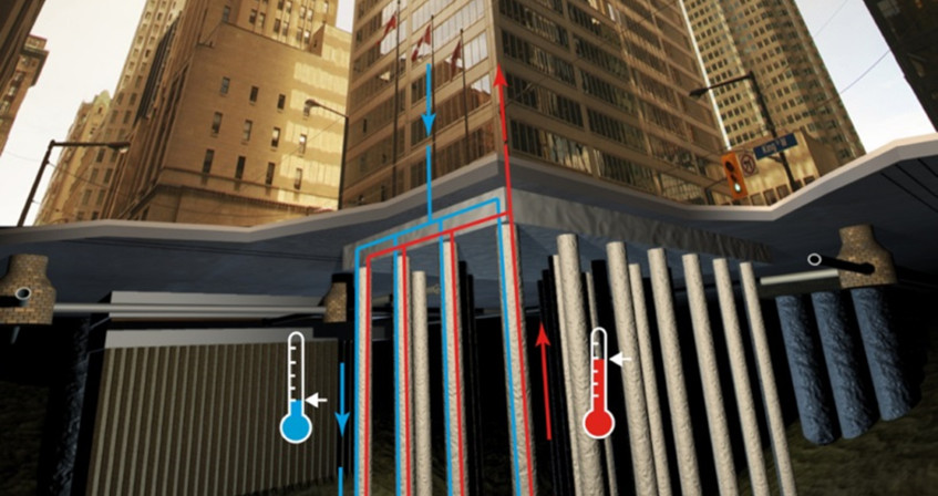
Energy geostructures are a modern application of low enthalpy geothermal systems (i.e. with low temperature differentials), with the major advantage of reducing initial installation costs compared to standard systems. The principle consists in setting up a network of pipes inside the reinforcement cages inside the concrete structures. A heat transfer fluid, which circulates in the pipe network, exchanges heat with the ground through the concrete. A heat pump adapts the temperature from the ground to that required to heat or cool buildings. The efficiency of the system must meet both energy (heat or cold production) and geotechnical-structural (limited additional stresses and displacements) criteria, which are highly dependent on the local conditions of the site hosting the construction.

In a world where energy needs are constantly increasing and where the research for green, local and renewable energy sources is becoming increasingly important, energy geostructures are perfectly suited. They represent an innovative and promising alternative for heating or cooling buildings and infrastructures.

1. What is an energy geostructure?

Geostructures, i.e. structures in contact with the ground can be used to exchange heat with the ground [1]. More precisely, the term geostructures includes piles for deep foundations, retaining wallstunnel lining segments, etc. The heat exchange between the ground and these concrete structures is ensured by a system of tubes arranged inside the structure and within which a heat transfer fluid circulates.

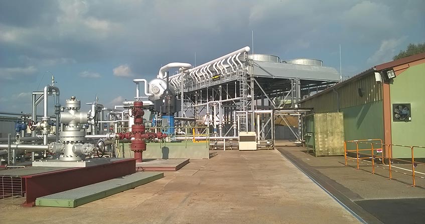
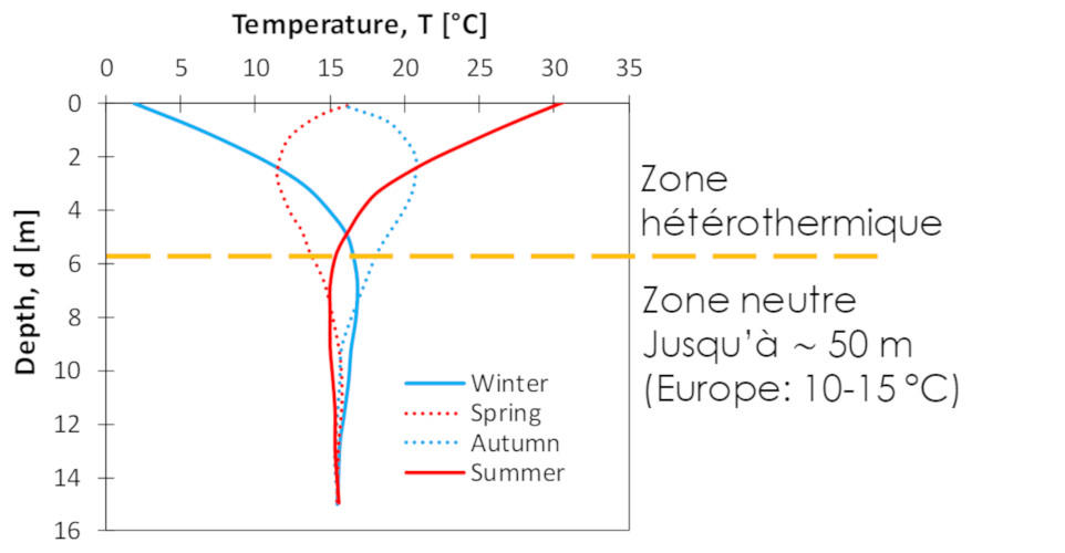
The principle is that of shallow geothermal energy: thanks to the fact that the subsoil temperature remains constant throughout the year (except for the first 5 to 8 m), this temperature will be higher than that of the external air in winter and lower in summer. This temperature difference allows heat to be extracted from the ground to the building during the winter (for heating purposes) and injected from the building to the ground during summer (for cooling purposes). This falls into the category of the so-called “low enthalpy” geothermal systems, i.e. systems that involve the first 100 m of ground and work with temperature variations of around 10 to 20 degrees Celsius. To adapt the temperature coming from the heat exchangers to that required to heat or cool buildings, these systems are connected to a heat pump (read Geothermal: a significant source of energy).

1.1. Operating modes

The system can be used for both heating and cooling of buildings (dual mode) as well as only for heating or only for cooling (single mode). The choice of the operating mode depends, among other things, on the local groundwater flow conditions.

  • In the case where groundwater flow is zero or very low, a thermal recharge of the soil is necessary in order to keep the temperature constant over the long term. In this case, it is strongly recommended to use the system in dual mode to ensure its efficiency.
  • If, on the other hand, the soil is sufficiently permeable (sand) and subjected to a groundwater flow greater than 0.5 or 1 m per day, the soil temperature is automatically rebalanced and a simple mode is possible [2].

On the other hand, if in the first case (no ground water flow) seasonal heat storage is feasible, in the second one (significant ground water flow) this is not possible and extraction is naturally decoupled from injection.

1.2. Technology diffusion

installations co2 reductions
Figure 1. Number of installations and CO2 reduction as a function of time [Source: Di Donna et al. 2017 (Ref.[3])]
Figure 1 shows the evolution of the number of energy geostructures installations over the last ten years, as well as the corresponding reduction in CO2emissions [3].The available data are probably not representative of all existing real cases, but the figure gives an overview of the interest in this technology and its benefits. Energy piles remain by far the most common application. This type of deep foundation is widely used to cross a layer of soil with poor mechanical properties and to lean on a rocky bedrock, for example.

dissemination energy geostructures world
Figure 2. Dissemination of energy geostructures in different countries [Source: © Di Donna]
Energy geostructures have developed in Europe and in the rest of the world since the 1980s. The first installations were realised in Austria, but the technology spread quickly to Switzerland, Germany, and England (Figure 2). In other countries, such as France and Italy, their social acceptance is still limited and their development is slower.

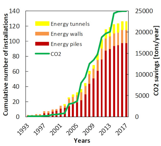
Energy geostructures have also been recently introduced in the United States and Asia. An example is the Shanghai Tower in China. It is the tallest tower in China with a height of 630 m, it rests on 2000 piles of 86 m in length and 1 m in diameter, about a hundred of which are equipped as energy piles.

1.3. Some examples of this are

In Europe, many projects have already been carried out in schools, private buildings or public buildings.

1.3.1. Energy piles

One of the most documented examples is probably the Terminal E at Kloten Airport (Zurich), which is operational since 2003. Designed by Amstein and Walthert AG, in partnership with ARGE ZAYETA, it is built on a clay and silty soil and its foundations consist of 350 drilled piles 27 m long and with a diameter between 90 and 150 cm. Of these, 306 are equipped as energy piles and provide 70% of the terminal’s heat requirements [4].The cooling of the building is also ensured by energy piles, 53% by free cooling and 15% by using the heat pump. In this specific case, the additional cost due to the instrumentation of the piles represented 0.3% of the building cost, which was paid back in 8 years.

1.3.2. Energy walls

Another classic example is the Lainzer Tunnel in Vienna, an energy tunnel built by the cut-and-cover method, where the excavation is first dug in the open air and then covered by concrete slabs. In this case, the heat is exchanged with the ground using the side walls, made of piles 20 m long and 120 cm in diameter. One out of three piles is equipped as an energy pile, which represents a total of 59 heat exchanger piles.

Also in Vienna, 4 sections of the U2 metro line are equipped with energy piles, invert and walls, for a total production of 449 kW of heating power and 231 kW of cooling capacity.

1.3.3. Energy tunnel

Energy tunnels are today the least developed application of this technology, despite their remarkable heat exchange potential. Indeed, the geothermal activation of tunnel linings (carried out either by mechanical excavation using a tunnel boring machine or conventional digging with a mechanical shovel) involves a larger volume of soil and therefore a generally larger exchange surface than piles.

The first example of an energy tunnel was built in Austria: the Janbach Tunnel. More recently, a full-scale experimental test was realised in the Turin metro tunnel in Italy.

1.4. Advantages

1.4.1. Economic

The main advantage of the installation of  energy geostructures over other conventional geothermal systems is that structural elements that are necessary for the structural stability and thus would be constructed in any case are use also for energy purposes. This results in a reduction of the initial installation costs. Experience shows a payback period included between 4 and 8 years, the initial investment being in the order of 2 to 4% of the cost of the work.

1.4.2. Environmental issues

seasonal evolution temperature
Figure 3. Seasonal evolution of subsoil temperature with depth. [Source: © Di Donna]
Like other conventional low enthalpy geothermal systems (horizontal and vertical probes), it is above all a local and renewable as well as a green energy source. Energy is produced from heat stored in the soil, which originates partly from our sun (heating the earth’s surface with solar radiation) and partly from the earth itself (heat flux from the earth’s core). This energy is transferred by the groundwater flow. The combination of these effects results in a seasonal fluctuation of the temperature of the first few meters of ground, as a function of the temperature of the external air (so-called heterothermic zone). Deeper, the temperature remains constant all over the year up to about 50 m depth (known as the neutral zone). From this depth, the temperature begins to rise at a rate of about 3°C every 100 m: this is called the geothermal gradient. Energy geostructures operate in the intermediate zone, the one at constant temperature, which in Europe is in the range between 10 and 15°C all year round (Figure 3). Their use can lead to a reduction in a building’s CO2 emissions of about 320 kg per kW produced (see Figure 1).

2. Energy efficiency

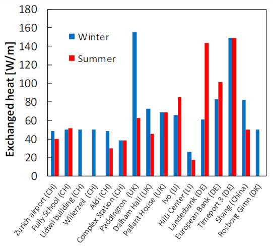
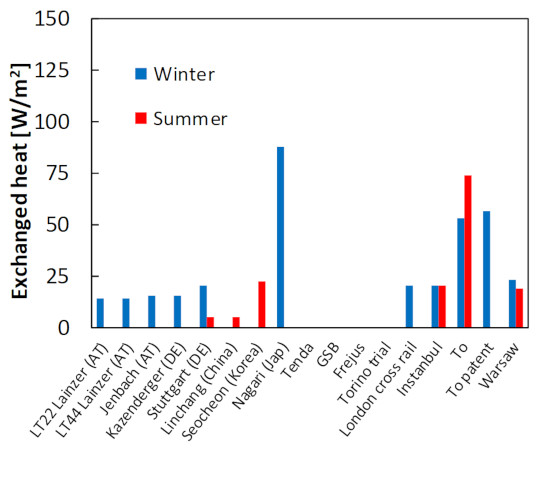
Figures 4, 5 and 6 summarize the heat exchange potential measured in operational energy geostructures, presented in Watt per metre of pile length and Watt per square metre of wall and tunnel surface, respectively.

2.1. Energy piles

energy piles
Figure 4. Heat exchanged by energy piles [Source: Di Donna et al. 2017 (Ref.[3])]
According to these data, except in rare cases, it is possible to extract between 20 and 100 Watt per meter of pile length. The order of magnitude is the same as that suggested by the English standards (BS 15450), which recommend considering between 30 and 50 W/m in fine soil (clays, silts) and between 55 and 80 W/m in coarse soil (sand, gravel). The numerous active installations and the geometric similarities with conventional geothermal probes have made it possible to acquire a precise knowledge of the behaviour of energy piles and to develop analysis methods that are now well established.

2.2. Energy walls and tunnels

energy walls
Figure 5. Heat exchanged by energy walls [Source: Di Donna et al. 2017 (Ref.[3])]
A limited number of examples is available for retaining walls and tunnels. According to the available data, it is possible to exchange between 10 and 30 Watt per square metre of wall or tunnel surface area. These values that might vary significantly depending on the soil properties (especially ground water flow), the geometry of the foundation and the operating conditions of the system.

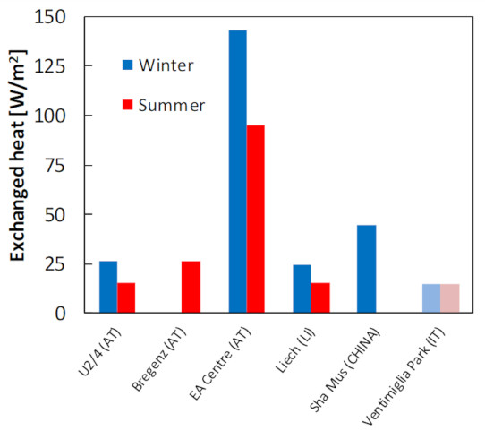
The numerical and analytical analysis of these structures is less straight forward due to the substantial difference with respect to geothermal probes. The main difference is represented by the boundary conditions on the excavation sides (for example inside a car park or tunnel or station). This obliges to take into consideration the heat exchange with the internal air as well. Moreover, the limited number of monitored cases makes things more complicated.

energy tunnels
Figure 6. Heat exchanged by energy tunnels [Source: Di Donna et al. 2017 (Ref.[3])]
Recent numerical studies on energy walls shows that the difference in temperature between the ground and the air inside the excavation significantly affects the heat exchange, especially over the long term.

3.Geotechnical aspects

geothermie
Figure 7. Temperature-induced stress, measured in situ [Source: Di Donna et al. 2017 (Ref.[3])]
The structural and geotechnical performance of energy geostructures remains their primary role and ensure it is of fundamental importance. For this reason, many studies have been carried out to understand whether using these structures as ground heat exchangers, by subjecting them to cycles of temperature variation, could affect their structural and geotechnical behaviour.

In other words, can the use of geostructures as ground heat exchangers induce additional displacements or reduce their load-bearing capacity (i.e. their ability to support applied loads such as the weight of a building)? Once again, the experimental and numerical results available concern mainly piles.

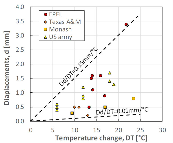
As a first approximation, a pile can be schematized as a vertical homogeneous bar. If we imagine heating it when it is completely free to deform, it will expand with respect to its center according to its coefficient of thermal expansion. To have an order of magnitude, let us consider a 30 m long pile, free to deform, and made of concrete, which has a coefficient of thermal expansion of about 10-5 °C-1. A temperature variation of 30 °C would induce a displacement of 4.5 mm (0.15 mm/°C) symmetrically at the top and at the bottom of it (and therefore at the head of the pile).

Figure 8. Temperature-induced displacements, measured in situ [Source: Di Donna et al. 2017 (Ref.[3])]
In reality, the pile is not free to expand, but its deformation is at least partially prevented by the surrounding soil and the upper structure. This reduces its free deformation and therefore its displacement at the head, but induces additional thermal stresses (compressive stresses in the case of pile heating). The additional stresses can be calculated as a first approximation as the product of the elastic modulus of concrete (read How the material deforms: fluids and solids) and the prevented deformation. Considering an elastic modulus for concrete of 30 GPa and assuming that the pile was completely blocked (all thermal deformation is prevented), this would correspond to an additional stress in the pile of 9 MPa, i.e. 300 kPa/°C.

Of course, these are two extreme cases. The reality is a in between them, but overall one could say that the more the pile will be free to expand, the more there will be a significant displacement at the head and the less thermal stress and vice versa. Similar considerations can be made for cooling.

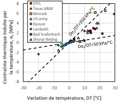
Figures 7 and 8 show the stress and displacement values induced by temperature variations, measured in full-scale tests carried out on energy piles. In practice, they can be used to have an order of magnitude of the effects that temperature changes induce on the geotechnical behaviour of real energy piles. It is important to note that, even if the thermal stresses look high, they remain well below the concrete strength.

4. Messages to remember

  • Energy geostructures represent a green, renewable and local source of energy for heating and cooling of buildings.
  • The main advantage with respect to other conventional closed geothermal systems (probes) is the significant reduction in initial installation costs, this reduction being due to the use of geostructures that would be constructed anyway.
  • This technology  is still under development, but the number of structures and buildings based on heat exchanger piles is increasing exponentially in Europe without any slowdown being expected at present.
  • The application to energy walls and tunnels is less developed, but many projects are ongoing to better understand their behaviour and energy efficiency.

Notes and references

Cover image. Laloui, L., and Di Donna, A. 2013. Energy geostructures: innovation in underground engineering. ISTE Ltd and John Wiley & sons Inc. [Source: © EPFL-LMS /M. NUTH 2010 ]

[1] Laloui, L., and Di Donna, A. 2013. Energy geostructures: innovation in underground engineering. ISTE Ltd and John Wiley & sons Inc.

[2] AIS. 2015. Use of ground heat by concrete foundation and support structures. Guide for design, implementation and maintenance. Swiss Society of Engineers and Architects. SIA DO 190 documentation.

[3] Di Donna, A., Barla, M., M., and Amis, T. 2017. Energy geostructures: a collection of data from real applications. In 15th IACMAG, Wuhan, China.

[4] Pahud, D. 2002. Geothermal energy and heat storage. SUPSI – DCT – LEEE Laboratorio di Energia, Ecologia ed Economia: 1-133.


The Encyclopedia of the Environment by the Association des Encyclopédies de l'Environnement et de l'Énergie (www.a3e.fr), contractually linked to the University of Grenoble Alpes and Grenoble INP, and sponsored by the French Academy of Sciences.

To cite this article: DI DONNA Alice (October 28, 2019), Geothermal energy, a source of green energy under our buildings, Encyclopedia of the Environment, Accessed July 27, 2024 [online ISSN 2555-0950] url : https://www.encyclopedie-environnement.org/en/soil/geothermal-energy-source-green-energy-buildings/.

The articles in the Encyclopedia of the Environment are made available under the terms of the Creative Commons BY-NC-SA license, which authorizes reproduction subject to: citing the source, not making commercial use of them, sharing identical initial conditions, reproducing at each reuse or distribution the mention of this Creative Commons BY-NC-SA license.

地热能,我们建筑下的绿色能源

PDF
geothermie - geostructures

  能源地下结构是低焓地热系统(即低温差)的一种现代应用,与旧系统相比, 具有降低初始安装成本的巨大优势。其原理是在混凝土结构的加固笼内建立一个管道网络,在管网中循环的传热流体通过混凝土与地面进行热交换,热泵将地面温度调整至加热或冷却建筑物所需的温度。这一系统必须满足能源效率标准(供热或制冷)和岩土结构标准(有限的附加应力和位移),这些都高度依赖于建筑所在位置的当地条件。

  当下世界对能源需求不断增加,绿色、本地和可再生能源的研究变得愈发重要的,能源地下结构与其完美契合。它代表着为建筑和基础设施供暖或制冷的一种具备创新性和光明前景的替代方案。

1. 什么是能源地下结构?

  地下结构,即与地面接触的结构,且可用于与地面进行热交换[1]。更准确地说,“地下结构”一词涵盖用于深地基的、挡土隧道衬砌段等。结构内部布置的管道系统保证地面和这些混凝土结构之间的热交换,传热流体在管道内循环。

  能源地下结构的原理是利用浅层地热能:底土温度全年保持稳定(除近地面5~8 米外),在冬季高于室外空气温度,在夏季则低于室外空气温度。利用这种温差可以在冬季将热量从地面提取并输入到建筑中(用于供暖),并在夏季将热量从建筑中释放到地层中(用于制冷)。这属于所谓的“低焓”地热系统的范畴, 即位于地下 100 米以内,温度变化范围在 10~20 摄氏度左右。为了使热交换器的温度与建筑物供暖或制冷所需的温度相匹配,这类系统会连接一个热泵(见“地热能:一种重要的能量来源”)链接。

1.1. 运行模式

  该系统既可用于建筑的供暖和制冷(双向模式),也可仅用于供暖或制冷(单一模式)。除此之外,运行模式的选择取决于当地地下水流动情况。

  • 在地下水不流动或流动很弱的情况下,为了长期保持底土温度恒定,需要对土壤进行热补给。在这种情况下,强烈建议系统采用双向模式,以保证系统的效率。
  • 另一方面,如果土壤具有足够高的渗透能力(砂土),并且地下水流速大于每天 0.5~1 米,那么土壤温度就会自动重新平衡,在这种情况下可以采用单一模式[2]

  另一方面,在第一种情况下(无地下水流), 季节性蓄热是可行的;在第二种情况下(大量地下水流),这是不可能的,提取热量自然与注入热量脱钩。

1.2. 技术渗透

环境百科全书-地热能-地下能源和二氧化碳
图1. 地下能源结构的安装量和二氧化碳减少量的历史变化[来源:Di Donna 等人,2017(参考[3])]

  图 1 显示了过去十年地下能源结构安装数量的变化,以及相应减少的 CO2 排放[3]。现有的数据或许不够全面,但该图还是反映了人们对这项技术的兴趣及这项技术的好处。目前,能源桩仍然是最常见的应用形式。这种深层地基被广泛用于贯穿力学性能差的土  层,直至达到基岩。

环境百科全书-地热能-地下能源结构情况
图2. 地下能源结构在不同国家的使用情况[来源:©Di Donna]

  自 20 世纪 80 年代以来,能源地下结构在欧洲和世界其它地区得到了发展。奥地利是第一个实现安装能源地下结构的国家,随后这项技术很快传播到了瑞士、德国和英国(图2)。在其它一些国家,如法国和意大利,对该技术的社会接受程度仍然有限,发展也比较缓慢。

  最近,美国和亚洲也引入了能源地下结构。譬如中国的上海中心大厦,它是中国最高的摩天大楼,高 630 米,建立在 2000 根长 86 米、直径 1 米的基桩上,其中约 100 根是能源桩。

1.3. 一些案例

  在欧洲,很多学校、私人建筑和公共建筑项目已经采用了这类技术。

1.3.1. 能源桩

  最有据可查的案例之一可能是自 2003 年开始运营的克洛腾机场(苏黎世)的 E 航站楼。该项目由阿斯顿(Amstein)、沃尔特(Walthert AG)及 ARGE ZAYETA 联合设计。航站楼建造在黏质和粉质土上,其地基位于 350 个钻孔桩之上,它们长 27 米,直径在 90 到 150 厘米之间,其中有 306 根为能源桩,能满足航站楼 70%供热需求[4]。能源桩还能满足建筑物的冷却需求,自然冷却满足了 53% 的制冷需求,另外 15%的制冷由热泵完成。在这个具体的案例中,安装能源桩产生的额外费用占建筑成本的 0.3%,在 8 年内就能收回。

1.3.2. 能源墙

  另一个经典案例是维也纳的莱恩泽隧道。这是一个采用随挖随填法构建的能源隧道,首先进行露天挖掘,然后再用混凝土板覆盖。在这种情况下,热量通过侧墙与地面交换,侧墙由长 20 米、直径 120 厘米的桩构成。每三个桩中就有一个为能源桩,即共有 59 个热交换桩

  同样在维也纳,U2 地铁线路的 4 个路段配备了能源桩、能源转换和能源墙,总生产供热功率达 449 kW,制冷量 231 kW。

1.3.3. 能源隧道

  能源隧道尽管具有非凡的热交换潜力,但目前还属于最不成熟的技术应用。实际上,隧道衬砌的地热能活化(无论是通过使用隧道掘进机进行机械挖掘还是使用机械铲进行常规挖掘)都涉及到更大体积的土壤,因此通常比桩的交换表面更大。

  能源隧道的第一个例子是在奥地利建造的延巴赫(Jenbach)隧道。较近期的例子出现在意大利,人们对都灵地铁隧道进行了一次全面实验测试。

1.4. 优势

1.4.1. 经济方面

  与其他传统地热系统相比,能源地下结构的主要优势在于结构要素是保证建筑稳定性的必要条件,因此在任何情况下都必须建造,同时又可以作为能源使用,这就降低了初始安装成本。经验表明,初始投资约为工程成本的 2%至 4%,投资回收期为 4 至 8 年。

1.4.2. 环境方面

环境百科全书-地热能-地下温度演变
图3. 地下温度随深度的季节演变。[资料来源:©Di Donna]

  像其他传统的低焓地热系统(水平和垂直探测)一样,地下能源系统首先是一种本土的、可再生的绿色能源。能量是由储存在土壤中的热量产生的,这些热量一部分来自太阳(太阳辐射加热地球表面),另一部分来自地球本身(地核的热流),能量则是通过地下水流动来传递的。这些因素的结合导致地下几米的温度随外部空气温度(所谓的变温区)出现季节性波动。在更深的地方,温度则全年保持不变,直到约 50 米深(称为中性区)。从这里开始,温度以深度每增加100 米上升 3°C 的速度变化:这被称为地热梯度。地下能源结构运作在中间区域, 即恒温区。在欧洲,该区域全年温度在 10 到 15°C 之间(图 3)。使用地下能源结构可以使建筑物的二氧化碳排放量减少约 320 千克/千瓦(见图 1)。

2. 能源效率

  图 4、图 5、图 6 总结了在运行的能源地下结构中测得的热交换势,分别以每米桩长的瓦特数、每平方米墙壁和隧道表面的瓦特数表示。

2.1. 能源桩

环境百科全书-地热能-能源桩的热交换
图4. 能源桩的热交换[来源:Di Donna 等人,2017(参考文献[3])]

  根据这些数据,除极少数情况外,每米桩长的功率可达 20 至 100 瓦特,与英国标准(BS 15450)建议的数量级相同。该标准的建议功率是在细土(黏质、粉质土壤)中为 30 到 50 瓦特每米,在粗质土(沙子,  砾石)中为 55 到 80 瓦特每米。能源桩与传统的地温探测仪几何形状相似, 大量安装和运行的地温探测仪使人们能够准确了解能源桩的特性,并发展出了成熟的分析方法

2.2. 能源墙和隧道

环境百科全书-地热能-能源墙的热交换
图5. 能源墙的热交换[来源:Di Donna 等人 2017(参考文献[3])]

  挡土墙和隧道的案例较少。根据现有的数据,每平方米墙壁或隧道表面积交换功率达 10 至 30 瓦特是可能的,具体数值可能会因土壤性质(特别是地下水流量)、地基的几何形状和系统的运行条件不同而发生显著变化。

  它们与地温探测仪有着本质上的不同,因而难以借鉴地温探测仪的数据直接分析这些构造的能量交换效率。两者的主要区别体现在边界的环境条件截然不同(如挡土墙的一侧可能是停车场、隧道或车站),同时还必须考虑到墙体与清空区内部空气的热交换。此外,由于监测的案例数量有限,使得分析更加困难。

环境百科全书-地热能-能源隧道的热交换
图6. 能源隧道的热交换[来源:Di Donna 等人,2017(参考文献[3])]

  近年来的数值模拟研究表明,能源墙一侧地下空间内的空气与地面的温差对能源墙热交换有显著影响,在长时间尺度上影响更大。

3. 岩土方面

  能源地下结构的主要作用仍然在于其构造性能和岩土性能,因此确保这些性能是极为重要的。基于此,许多研究通过施加周期性的温度变化,分析是否会影响其结构和岩土工程性能,进而判断能否将这些结构作为地热交换器使用。

环境百科全书-地热能-原位测量的温度诱导应力
图7. 原位测量的温度诱导应力[来源:Di Donna 等人,2017(参考文献[3])]

  换言之,使用地下结构作为地热交换器是否会引起额外的位移或减弱它们的承载能力(即其承受建筑物的重量等荷载的能力)? 需要再次强调的是,现有的实验和数值模拟都主要针对基桩结构。

  作为一级近似处理,一根桩可以被简单看作一个均匀的直杆。如果我们想象在它可以完全自由形变的时候加热它,它就会基于其热膨胀系数相对于其中心膨胀。为了有一个数量级的概念,让我们设想一根 30 米长、可自由形变的混凝土桩,其热膨胀系数约为 10-5 °C -1,30°C 的温度变化将从桩顶到桩底均匀地(因此特别是在桩头) 引起 4.5 mm(0.15 mm/°C )的位移。

环境百科全书-地热能-原位测量的温度诱发位移
图8. 原位测量的温度诱发位移[来源:Di Donna 等人,2017(参考文献[3])]

  而在现实中,桩体不能自由膨胀,其形变至少部分受到周围土壤和上部结构的阻碍,这减弱了其自由形变以及其顶部的位移,但会引起额外的热应力(在桩加热的情况下为压缩应力)。附加应力可以用混凝土弹性模量(见“物质是如何变形的——流体和固体”)和形变减少量的乘积的一阶近似来计算。若混凝土的弹性模量为 30 GPa,假设完全禁锢(不能发生任何热变形),则桩的内部会承受附加应力为 9 MPa,即为 300 kPa/℃。

  当然,这是两个极端的例子。实际情况介于两者之间,但总体而言,可以认为桩自由膨胀的程度越大,就会在顶部产生更为显著的位移以及更小的热应力,反之亦然。冷却时也可以做出类似的推测。

  图 7 和图 8 显示了在实物试验中温度变化时能源桩上产生的应力和位移值。这类实验中可测试一个数量级的温度变化对真实能源桩的岩土工程性能的影响大小。值得注意的是,虽然热应力看似很大,但实际上远低于混凝土强度。

4. 需记住的要点

  • 能源地下结构是一种绿色的、可再生的本地能源,用于建筑物供暖和制冷。
  • 由于直接利用了建筑本身需要建造的支撑结构,因而与其它传统封闭式地热系统(探测器)相比,能源地下结构的主要优势是显著降低初始安装成本
  • 这项技术仍处于发展阶段,但在欧洲,应用热交换桩的结构和建筑数量呈指数增长,目前尚未出现增长减缓的迹象。
  • 能源和能源隧道的应用仍不太成熟,但已经有许多项目正在测试这类结构,以便更好地了解它们的性能和能源效率。


说明及参考文献

封面图片:Laloui, L., and Di Donna, A. 2013. Energy geostructures: innovation in underground engineering. ISTE Ltd and John Wiley & sons Inc. [Source: © EPFL-LMS /M. NUTH 2010 ]

[1] Laloui, L., and Di Donna, A. 2013. Energy geostructures: innovation in underground engineering. ISTE Ltd and John Wiley & sons Inc.

[2] AIS. 2015. Use of ground heat by concrete foundation and support structures. Guide for design, implementation and maintenance. Swiss Society of Engineers and Architects. SIA DO 190 documentation.

[3] Di Donna, A., Barla, M., M., and Amis, T. 2017. Energy geostructures: a collection of data from real applications. In 15th IACMAG, Wuhan, China.

[4] Pahud, D. 2002. Geothermal energy and heat storage. SUPSI – DCT – LEEE Laboratorio di Energia, Ecologia ed Economia: 1-133.


The Encyclopedia of the Environment by the Association des Encyclopédies de l'Environnement et de l'Énergie (www.a3e.fr), contractually linked to the University of Grenoble Alpes and Grenoble INP, and sponsored by the French Academy of Sciences.

To cite this article: DI DONNA Alice (March 12, 2024), 地热能,我们建筑下的绿色能源, Encyclopedia of the Environment, Accessed July 27, 2024 [online ISSN 2555-0950] url : https://www.encyclopedie-environnement.org/zh/sol-zh/geothermal-energy-source-green-energy-buildings/.

The articles in the Encyclopedia of the Environment are made available under the terms of the Creative Commons BY-NC-SA license, which authorizes reproduction subject to: citing the source, not making commercial use of them, sharing identical initial conditions, reproducing at each reuse or distribution the mention of this Creative Commons BY-NC-SA license.