

Soils for engineers
PDF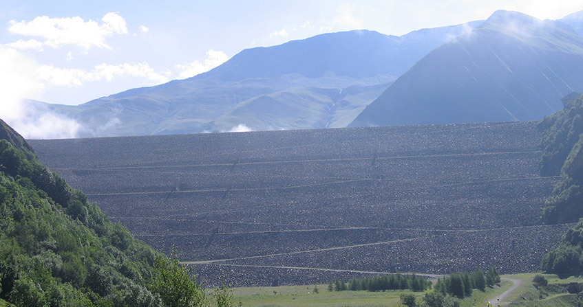
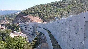
The very diverse soils on our planet require the expertise of specialized engineers to carry out civil engineering projects, in conjunction with other specialists. This specialist highlights the soil properties to be taken into account and characterizes them with appropriate tests, so that the foundations of civil engineering structures are sufficiently stable, with a safety reserve. Particular attention is paid to design tools for modelling the soil-structure interaction during the life of a structure. The inspection of the surrounding site provides a permanent record of the condition and possible movements of the supporting soil of a building throughout its life. Today, at the cost of soil improvement and reinforcement work, very large structures can be built in areas that were once considered unsuitable for any particular location. Current construction methods, which are less and less disruptive in urban areas in particular, make it possible to push the limits of what is possible beyond what was once imaginable.
1. Why soils require attention
A specialized engineer (the geotechnical engineer and more often a team of geotechnicians) is in charge of the interaction between soil and structure (soil-structure interaction). He is of course in close contact with the team responsible for the work itself. In the rest of this text on soils, we will use the term engineer to refer to the geotechnical engineer.
When the idea of a major civil engineering structure, useful in principle, comes up, part of the preliminary project consists in closely examining the entire environment it will undergo and modify. We must therefore consult the annals of local natural phenomena likely to affect the deformations and stability of the construction over time (rain, snow, drought, flood, storm, freeze-thaw, earthquake, explosion,…). But a broad impact study (physical, hydraulic, ecological, socio-economic,…) is also essential to assess the repercussions of the structure on the nearby and distant site. The interests of individuals and the general interest are often in conflict. For example, the installation of the Aswan dams has completely changed the conditions of agriculture in Egypt: beneficial effects in the Upper Nile Valley (irrigation), but disastrous on the Lower Valley (salinization of land, lack of fertile annual alluvium).
So, if there is nothing fundamentally wrong with construction, we enter the project phase (the precise design of the structure and its interaction with the ground).
2. Important soil properties and their characterization
The essential tool of the soil engineer in charge of a civil engineering project is mechanics. Therefore, its most examined properties are its mechanical and hydraulic properties, namely its rigidity (modulus of elasticity), its strength (cohesion and friction), its dilating or contracting tendency to rupture, its permeability, and its reaction to hydration/dehydration. The anisotropy of these properties is always considered. The pore pressure in a soil leads the engineer to consider the total stresses and the effective stresses, the latter being those actually supported by the soil skeleton.
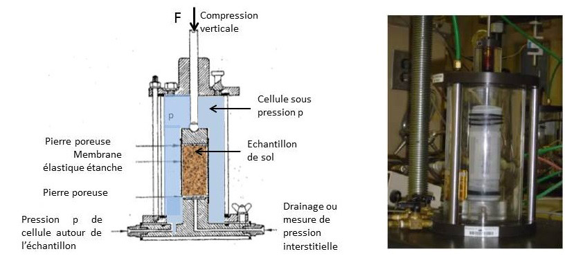
Laboratory tests directly provide hydro-mechanical data. On the other hand, in situ tests can only be interpreted by correlations with hydro-mechanical parameters, with a certain uncertainty. Soundings, penetrometer tests, pressuremeter tests provide local information (according to a vertical), while well-conducted seismic tests provide information about the ground in its mass, highlighting its heterogeneities. Many other techniques are available to characterize the subsoil layers: electrical conductivity, gravimetry, radar, which also help to detect cavities and discontinuities – faults, fractures –.
3. Design tools for soil
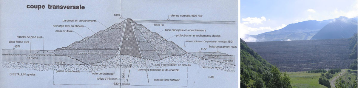
Classically, we talk about the structure in project (the bridge, the dam, the power plant,…), and the ground that must support it or even constitute it (earth dam, for example). During the life of the structure, the soil-structure interaction is permanent.
Equipped with the characteristics of the local soil (§ 2), the engineer evaluates the service and exceptional loads of the structure on the ground. Then the project is defined and the structure is completely dimensioned by ensuring one or more safety factors, obtained by estimating failure scenarios by increasing the loads or by reducing the soil characteristics. National and international standards (including Eurocodes, Eurocode 7 for soils) have been developed and gradually refined to assess safety, taking into account duly recorded and meditated historical disorders and accidents. But the actual deformations of the ground and the structure, before any failure, are also relevant in terms of the health of the structure.

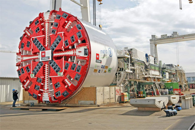
We have just mentioned numerical modelling (finite elements) as a good predictive tool for the engineer. But the prediction can only be satisfactory if the hydro-mechanical data that feed it are representative. However, the initial characterisation of the soils (§ 4), at the time of the project, is always approximate, simply because of the heterogeneity of the subsoil. For example, miners digging a tunnel or a gallery tell you that they really only know the ground they are crossing when they excavate it, when they are driving it. This is where the power of finite element numerical modelling can be harnessed. The phasing of the work (the successive stages of construction) is simulated, the results of which are compared with on-site measurements during this work, from the beginning (the virgin site), of the modifications of the hydro-mechanical variables of the soil (displacements, stresses, interstitial pressures,…). This provides the basis for an inverse analysis, allowing the soil project parameters to be corrected as the construction progresses. This results in a more realistic definitive simulation of the structure’s behaviour in service and under exceptional loading. This so-called observational methods also make it possible to rethink the initial project, in case it has been too bold, to the point of no longer meeting the safety criteria.
4. The auscultation of structures and soils
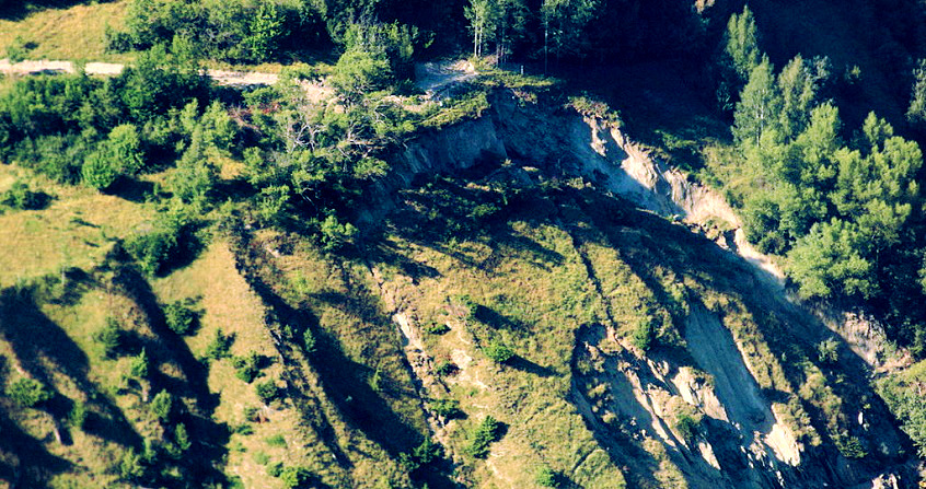
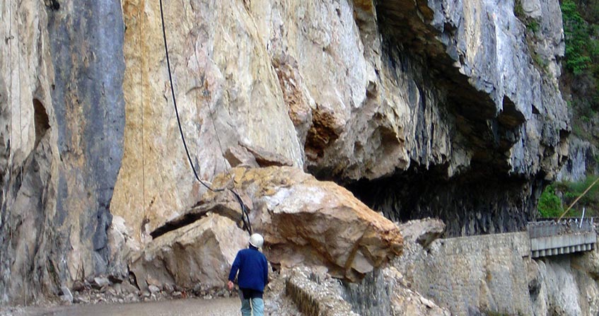
The measures accompanying the construction of the structure, on the ground and on the structure itself, have just been mentioned (§ 3). But a structure and its site have a very long life, after construction. For large structures, as well as for ongoing and identified risk situations (landslides, rockfalls,…), programmed measurements of site hydro-mechanical variables are common, constituting the auscultation. To be useful, this approach requires rapid interpretation and dissemination in real time. Thus, on a landslide, an acceleration of movements without modification of loads means a rapid evolution towards sudden rupture, and must trigger the alert of threatened populations. The structures (and their sites) commonly ausculted are dams (and the slopes of their valleys), power plants, bridges and viaducts (for which differential settlements are feared), tunnels and galleries (for which limited convergence is ensured, resulting from the movement of the faults crossed, or from the alteration of the surrounding rock. The devices installed are extensometers, inclinometers, settlement, pore pressure and groundwater level sensors, topographic survey tools,..
In the past (on the scale of the century(s)), the engineer had at his disposal rough measuring instruments (theodolite for displacements, level for inclinations,…). We are nowhere near these proven measurement technologies. New technologies have a prominent place in geotechnical engineering. Today, topographic movement measurements are carried out quickly, automatically and precisely using GPS. Extensometric and inclinometric measurements use optical fibre. In tunnels or galleries, all guidance and convergence measurements are based on laser techniques. UAVs and image analysis techniques are used to monitor the condition of large facings (dams, bridges, etc.). And many other new technologies are expected to be included in the panel of auscultation tools.
5. Soil improvement and reinforcement

The most widely used technique worldwide to compensate for differential settlement is the injection of cement grout under foundation areas with excess settlement. But another original technique has recently developed. The worrying and increasing inclination of the Tower of Pisa and Mexico City Cathedral, built on a thick layer of clay, has been treated, in part, by under-excavation, or clay extraction under the highest foundation area. The recovery of these buildings was not intended, but rather the stabilization of their inclination (in addition to technical prudence, the tourist manna must be protected…).
6. Current trends and performance
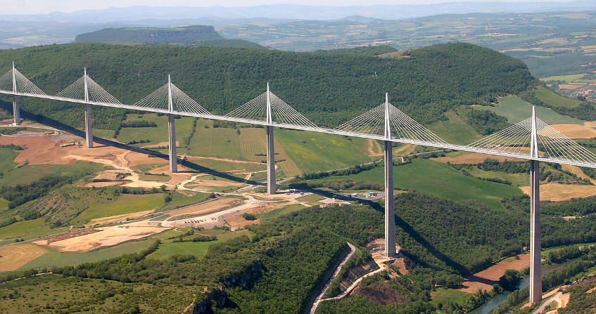
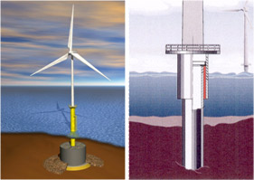
Piles are the preferred foundation methods in soft ground, drilled or driven, commonly reaching several metres in diameter and a hundred metres in length in offshore. Cyclic loads are actively studied due to the so-called cyclic degradation phenomenon. To the extent that the capacity of the foundations is almost unlimited, provided that the price is paid, the structures themselves change in nature. For example, self-stable cable-stayed bridges and viaducts (Millau, Rion-Antirion,…) take precedence over suspension bridges
Today, on land, we are experimenting with geothermal piles and structures, with a dual function, foundation and heat exchanger.
Many other innovations are to come, which will mobilize the new generations..
References and notes
Cover image. The Grand’Maison dam by Douchet Quentin[GFDL or CC BY-SA 3.0], via Wikimedia Commons
The Encyclopedia of the Environment by the Association des Encyclopédies de l'Environnement et de l'Énergie (www.a3e.fr), contractually linked to the University of Grenoble Alpes and Grenoble INP, and sponsored by the French Academy of Sciences.
To cite this article: BOULON Marc (January 5, 2025), Soils for engineers, Encyclopedia of the Environment, Accessed July 25, 2026 [online ISSN 2555-0950] url : https://www.encyclopedie-environnement.org/en/soil/soils-for-engineer-2/.
The articles in the Encyclopedia of the Environment are made available under the terms of the Creative Commons BY-NC-SA license, which authorizes reproduction subject to: citing the source, not making commercial use of them, sharing identical initial conditions, reproducing at each reuse or distribution the mention of this Creative Commons BY-NC-SA license.