


Soil erosion: a story of fluid and grains
PDF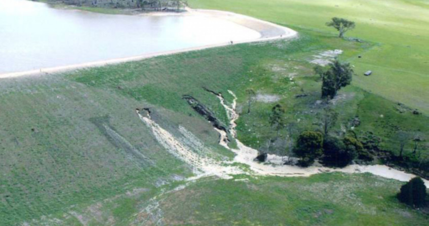
No material is so hard that it can withstand the onslaught of time without eroding. Water and wind patiently sculpt all the obstacles that stand in their way, whether natural or man-made. The issue of soil erosion by surface or deep water flow is addressed here through the problem of the resistance of embankment dikes and dams to water infiltration or water flow on their surface. A typology of the different possible erosion mechanisms is proposed. The characterization of the resistance properties of a soil to erosion is then evoked, as well as some design rules to curb erosion. The concepts discussed in this article are illustrated by examples of disorders observed on real structures, as well as by laboratory and field experiments, and by numerical simulations.
1. Eternal competition between soil, air and water
Water and wind shape our landscapes. On large scales, water falls as precipitation, the intensity of which can destructure the soil and wash it away by runoff. The water then forms torrents and rivers which, by transporting huge quantities of sediment, incise the landscape by creating valleys. Along the coastline, the repeated onslaught of waves changes the coastline as storms roll in. In gusts of wind, the wind moves dunes and raises clouds of dust that sometimes redeposit several thousand kilometres away (the sand of the Sahara, for example, is capable of crossing the Atlantic).
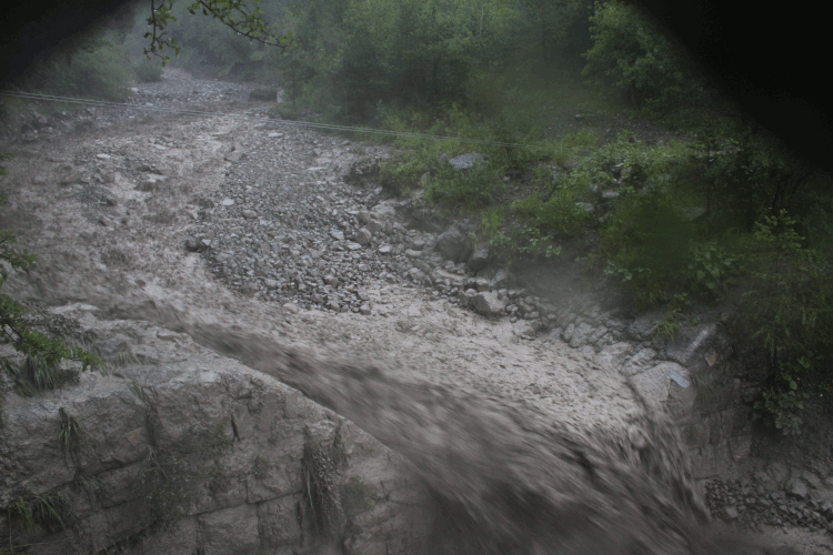
By building dikes and dams, man has been able to control the impact of water on his environment more and more effectively. Although today we often think of them as concrete structures, most of the existing dikes and dams are made of fill, i.e. compacted earth. These structures protect us, for example, from the onslaught of floods and storms, but they can also guarantee us a resource of water (drinking or irrigation water) and energy. Like all human constructions, they are not indestructible and are also subject to erosion. In this article, we propose to present the issue of soil erosion from the particular angle of erosion of dikes and dams (Figure 1). In this sense, the article is not intended to be exhaustive and does not address many issues such as soil desertification or the erosion of agricultural land [1]. It nevertheless presents soil erosion mechanisms that are far from being specific to dikes and dams alone, as well as the strategies developed to study them and limit their effects.
2. Different modes of erosion of dikes and dams

Internal and external erosion are responsible for about 50% and 45% of embankment dam failures, respectively, according to worldwide statistics [3]. However, the conditions of their occurrence, as well as their speed of development and their consequences in terms of the embrittlement of the structures they affect are still largely open questions, and much research is currently being carried out on the subject. In the current state of knowledge, it is therefore not possible to justify by calculation the resistance of an embankment dam in the event of uncontrolled overflow of the reservoir, even if experience shows that the dam can resist provided that the overflow does not last too long.
With regard to internal erosion, the work carried out over the last fifteen years or so has led to a classification, widely shared in the scientific community, into four mechanisms [4]. A distinction is made between regressive erosion, conduit erosion, contact erosion and suffusion.
- Backward erosion corresponds to the entrainment from downstream of the material at the outlet of the internal flow. It is triggered by an internal flow in the ground that emerges perpendicular to the soil/water interface and is manifested by the appearance of “sand boils” (Figure 2). If the flow is too intense, the soil grains closest to the surface are washed away. Water laden with suspended particles gushes out of the soil. As the flow slows down, the particles redeposit themselves and small mounds, similar to miniature volcanoes, are often observed. If this process continues over time, the particles deposited come from increasingly distant areas and, as time goes on, an erosion conduit is created from downstream to upstream.
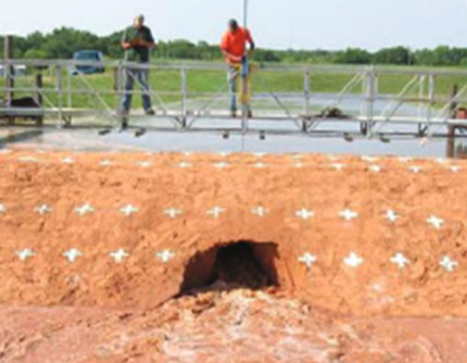
- Piping erosion (or concentrated flow erosion) is the widening of a pre-existing conduit [5], such as a burrow, a crack, poor compaction along a pipeline or a conduit left by root decomposition. The water flowing through the pipe exerts shear forces at its edges that can pull material off the surface if the flow is sufficiently intense. The diameter of the conduit thus increases gradually, allowing an increasingly large flow of water to pass through, which will sustain the phenomenon until it encounters a stronger material or until the collapse of the conduit is observed (Figure 3).
- Contact erosion occurs at an interface between fine and coarse soil when water flows either parallel to the interface or from the fine to the coarse material. When the flow is strong enough, the fine material can be eroded if the grains of the fine material are small enough to squeeze between the coarse grains of the coarse material. If the layers of material are arranged horizontally, contact erosion usually causes settlement (Figure 4).
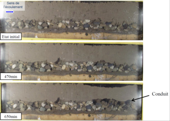
- Suffusion is the selective erosion of the smallest grains in a soil. In a granular material (Read: Sand: fluid or solid?), not all the grains are stressed in the same way to take up the mechanical stresses that are applied to the soil. Only a small fraction of the grains (barely 20%) transmit the main mechanical stresses. The other grains are only slightly stressed and can then easily be set in motion by an internal flow of water. If the granulometry (i.e. the distribution of grain sizes) is such that the smallest soil grains can circulate between the largest soil grains, a fraction of the soil will be able to erode under the effect of this internal flow. The soil in place then becomes more porous until it eventually collapses in on itself or encourages the establishment of other erosion mechanisms as the flow intensifies. In practice, this mechanism is difficult to demonstrate because the traces of suffusion are hardly visible before a break and are then completely erased by the break. Nevertheless, the phenomenon can be demonstrated in the laboratory.
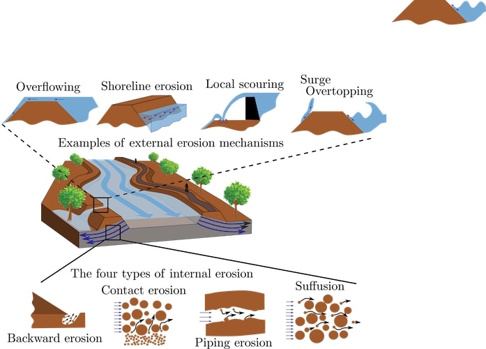
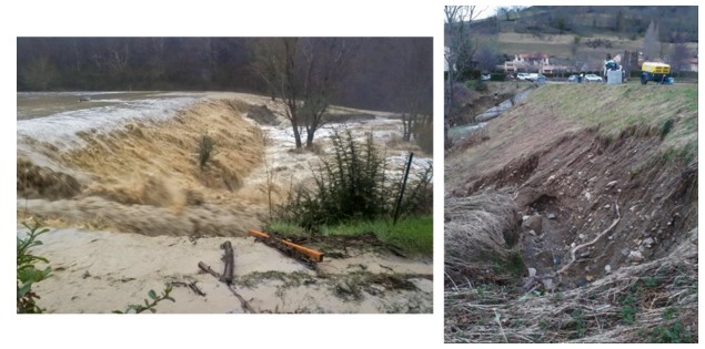
- Overflowing corresponds to the overflow of the water level over the crest of a dyke or dam. The result is an intense flow over the ground surface. The shear forces exerted by the water can then pull out grains and carry them along with it. This is certainly the most feared and spectacular erosion mechanism in relation to the failure of dams or embankments.
- Shoreline erosion mainly concerns river dikes subject to the action of the river’s current and more generally river banks. In this case, the water flows parallel to the axis of the structure. Even if locally the fluid/grain interaction is similar to overflow (a flow of water on the ground surface), bank erosion involves less intense shear forces. On the other hand, they are more constant over time and can weaken the dike or bank that is subject to them in the long term.
- Local scouring is the action of a jet of water on the ground following, for example, an overflow over a rigid structure. This type of concentrated flow, which impacts the ground perpendicularly to its surface, will locally dig into the ground. Once the process has begun, the recirculation of water and the eddies at work in the basin can help to maintain the erosion active.
- Wave erosion is visible either by surge or by overtopping. Wave surge corresponds to the repeated action of waves breaking over an obstacle, much like on the beach. A dam or dyke prevents waves from spreading over the surface of a body of water and causes them to break. This surge generates energy that can sometimes destructure the impacted material and put grains in suspension. Overtopping corresponds to the flow of packets of water downstream of an obstacle following the breaking of waves large enough to reach the crest of the obstacle. It is this phenomenon that generates water sheaves that are as spectacular as they are dangerous during seaside storms. As the water falls back to the ground, it may have enough energy to carry some material with it. The energy levels involved in the overtopping are lower than in the surge, but the soils impacted are often less well protected because they are on the downstream side of the structure.
3. Characterize soil erodability
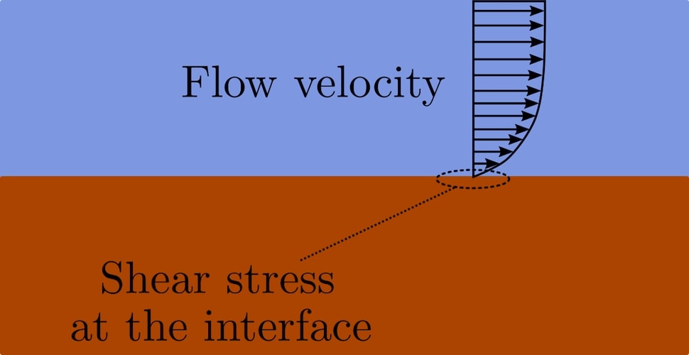
In the case where an interface between a solid and a fluid domain can be distinguished, and the fluid flows parallel to this interface, the erosion can be characterized as surface erosion at the material scale. The intensity of the flow is then characterized by the shear stress exerted by the fluid at this interface. The resistance of a soil to flow is characterized by the cohesion of the material as well as by its volume weight. This leads to the writing of a criterion for the initiation of erosion by comparing driving forces and resistant forces. The kinetics of erosion then results on the one hand from spatial fluctuations in the mechanical properties of the soil and on the other hand from spatio-temporal fluctuations in the fluid stresses at the interface, the latter being partly due to turbulence.
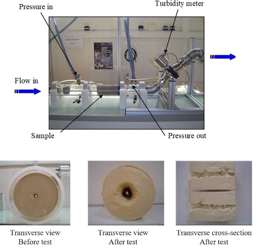
A few laboratory tests exist today to characterize the erodability of a material, both in terms of the occurrence of the phenomenon (from which flow intensity) and the kinetics (at which speed a material erodes). These tests include the HET [8] (Hole Erosion Test) (Figure 7) adapted to the study of pipe erosion, the JET [9] (Jet Erosion Test) and the EFA [10] (Erosion Function Apparatus) adapted to the study of external erosion, or the suffusion permeameter adapted to the study of internal suffusion erosion. The interpretation of the first three devices is based on a surface erosion model (other models exist [11]) based on two parameters: an erosion coefficient (characterising the erosion kinetics) and a critical fluid stress (characterising the erosion initiation). The interpretation of the suffusion test is still missing of a well-established theoretical framework and remains, for the time being, a trial for research purposes only.
4. Some good practices to limit internal and external erosion
Knowledge of the various internal erosion mechanisms makes it possible to devise strategies to limit the action of water on the soil. These require the formulation of a certain number of “good conduct” rules. For dams and dikes, these rules, called recommendations, are written by the profession within national and international committees. These include the French Committee on Dams and Reservoirs (CFBR [15]) and the International Commission on Large Dams (ICOLD [16]).
Feedback teaches us that it is much easier to prevent than to heal because, once erosion has started, it is difficult to stop it before the structure concerned breaks. For example, the emblematic failure of the Teton Dam [17] in the United States in 1976 occurred only a few hours after the first leaks were detected and despite desperate attempts to repair it.
First of all, the choice of materials used to erect an embankment must be adapted to the hydraulic stresses to which it will be subjected. If, despite everything, the hydraulic stresses generated in a crisis situation are too intense, protection measures aimed specifically at limiting the hydraulic stress on the most fragile materials can be implemented (Read: Soil reinforcement: techniques that have become essential). Here are a few examples of strategies that can be implemented (this list is of course not exhaustive):
- The use of low-permeability clay materials limits the intensity of flows infiltrating the soil and reduces the likelihood of internal erosion (Read: Clays: a surprisingly natural nanomaterial).
- The respect of filter criteria between different materials in contact and the respect of self-filtration criteria for each material limits the risk of observing contact internal erosion or suffusion. If these criteria cannot be met, the use of geotextiles to be placed between the two soil layers in question can be used.
- Maintained vegetation and control of burrowing animals will limit the presence of conduits conducive to piping erosion.
- The intrinsic resistance of a soil to erosion can be improved through chemical processes (lime treated soils, mixing with a bentonite and cement slurry,…) or biochemical processes (soil bio-calcification) which increase the cohesion between the elementary soil grains.
- Grass cover (or low vegetation) limits the shear stress exerted by a runoff at the soil surface (increase in the thickness of the boundary layer [18]) and thus delays the onset of erosion. The presence of vegetation also limits the destructuring of the soil by the splash effect during heavy rainfall or when waves pass over it.
- The placement of riprap acts as a shell to the waves and dissipates their energy before they reach the finer materials.
- The installation of a counter-reservoir downstream of a structure subject to regressive erosion limits the difference in water level between upstream and downstream and therefore the intensity of internal flows. This is why, for example, sandbags are placed around a “sand boil” during a crisis situation.
5. What future for dam and dyke protection technology?
Today a typology of soil erosion by water flow exists with regard to internal erosion (regressive erosion, conduit erosion, contact erosion and suffusion). On the other hand, the classification of external erosion mechanisms is still under discussion by the profession and the four mechanisms presented in this article should be considered only as a first basis for reflection.
A number of construction techniques are used to limit as much as possible the action of water on erodible soil. These techniques are based on the current state of scientific knowledge, which has not yet been completely stabilised. The understanding of the physics of erosion certainly remains a widely open problem and a very active field of research.
As for the geomorphological erosion mentioned in the introduction, this is the result of a wider range of phenomena with visible consequences over much longer periods of time. The erosion mechanisms mentioned in this article are of course involved in the shaping of landscapes, but we could add to them landslides, various chemical alterations, freeze/thaw cycles, sediment transport, glacial creep, wind transport, impact of vegetation, etc.
6. Messages to remember
- Under the action of a fluid (water or air), soil (natural or man-made) can erode either on its surface at the interface with the fluid flow, or in its volume under the action of water infiltration.
- All earth structures are permeable and subject to erosion. A good design and a good follow-up make it possible to limit the phenomenon and to be able to start work in time in the event of disorder noted.
- Soil erosion is still a very active research topic, whether from the point of view of understanding the physics of the different erosion mechanisms, characterizing the resistance properties of soils and the development speeds of the different mechanisms, or even technologies for detecting, measuring and monitoring in situ erosion.
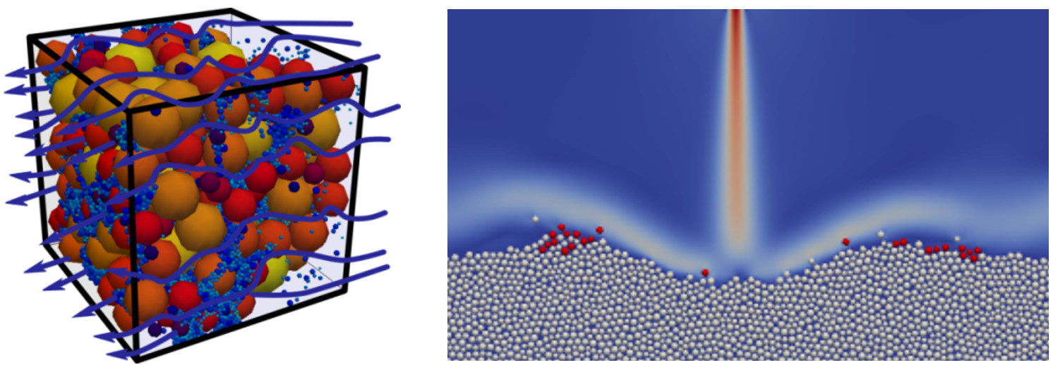
- The research is based on laboratory experiments (on the scale of the material), field experiments (on the scale of the work) and digital simulations (digital experiments).
Notes and References
Cover image. (Blackman dam, Tasmania, 2005. Photo Credit: The Mercury and Kim Eiszele)
[1] Van Oost, K. et al. 2007. The impact of agricultural soil erosion on the global carbon cycle. Science, 318, (5850), 626-629.
[2] This is still sometimes referred to as the hydraulic fox.
[3] Foster, M. et al. 2000. The statistics of embankment dam failures and accidents. Canadian Geotechnical Journal, 37, 1000-1024.
[4] Bonelli, S. (2012). Erosion of geomaterials. Hoboken: John Wiley & Sons
[5] This type of erosion is thus only found in cohesive materials that allow a conduit to exist without collapsing.
[6] Hanson, G. et al. 2010. Internal erosion and impact of erosion resistance. Collaborative management of integrated watersheds. Proc. of 30th annual USSD conference, 773-784.
[7] Beguin, R. (2011). Multi-scale study of contact erosion in earthen hydraulic structures. PhD thesis. University of Grenoble.
[8] Benahmed, N. and Bonelli, S. (2012). Investigating concentrated leak erosion behaviour of cohesive soils by performing hole erosion tests. European Journal of Environmental and Civil Engineering, 16(1), 43-58.
[9] Hanson G. J. and Cook K. R. (2004). Apparatus, Test Procedures and Analytical Methods to Measure Soil
Erodibility In Situ. Engineering in Agriculture, ASAE, 20(4), 455-462.
[10] Briaud, J. L. et al. (2001). Erosion function apparatus for scour rate predictions. Journal of geotechnical and geoenvironmental engineering, 127(2), 105-113.
[11] Knapen, A. et al. 2007. Resistance of soils to concentrated flow erosion: A review. Earth-Science Reviews, 80(1-2), 75-109.
[12] https://en.wikipedia.org/wiki/Discrete_element_method
[13] Wautier, A. (2018). Micro-inertial analysis of mechanical instabilities in granular media, application to internal erosion. PhD thesis. Aix-Marseille University.
[14] Benseghier, Z. (2019). Numerical study of the erosion of a cohesive granular material by fluid flow. PhD thesis. Aix-Marseille University.
[15] https://www.barrages-cfbr.eu/
[16] https://www.icold-cigb.org/
[17] https://fr.wikipedia.org/wiki/Barrage_Teton
[18] Size of the area over which a flow passes from zero velocity to its maximum velocity as shown in Figure 2.
The Encyclopedia of the Environment by the Association des Encyclopédies de l'Environnement et de l'Énergie (www.a3e.fr), contractually linked to the University of Grenoble Alpes and Grenoble INP, and sponsored by the French Academy of Sciences.
To cite this article: WAUTIER Antoine (January 5, 2025), Soil erosion: a story of fluid and grains, Encyclopedia of the Environment, Accessed July 28, 2026 [online ISSN 2555-0950] url : https://www.encyclopedie-environnement.org/en/soil/soil-erosion-story-fluid-grains/.
The articles in the Encyclopedia of the Environment are made available under the terms of the Creative Commons BY-NC-SA license, which authorizes reproduction subject to: citing the source, not making commercial use of them, sharing identical initial conditions, reproducing at each reuse or distribution the mention of this Creative Commons BY-NC-SA license.