

Archimedes’ thrust and lift
PDF
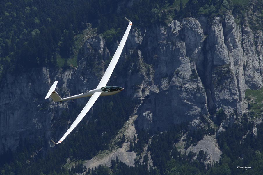
To compensate for their weight, the gigantic cargo ships that travel the oceans benefit from Archimedes’ thrust. But why are they so stable and never tip over, even when the sea is rough? By comparison, birds, planes and gliders, much heavier than air, seem to perform extraordinarily well when flying, like the majestic vulture in the cover image. We will see that it is their movement that generates a force, called lift, that can compensate for their weight.
1. A look back at Archimedes’ weight and thrust
As soon as it is released, the stone falls to the ground, attracted by its weight. Its fall stops when its support on the ground provides it with a force exactly opposite to its weight, which is called the reaction of this support (link to the article The laws of dynamics). The rock is back in balance.
Bodies immersed in a fluid medium, such as air or water, are subjected to pressures on their periphery, the overall effect of which at rest is reduced to Archimedes’ thrust [1], equal to and opposite to the weight of the fluid displaced. In the example of the stone released into the air, this thrust is much lower than its weight, since the density of the air is about 3000 times lower than that of a stone. The released rock therefore accelerates strongly, in accordance with the fundamental law of dynamics. On the other hand, a balloon falls more slowly than the rock and can even rise if it is inflated with a gas lighter than air, such as helium or hydrogen. In water, the stone also falls but much slower than in the air. At the beginning of its fall, this is due to the fact that Archimedes’ thrust is still unable to compensate for its weight, but the imbalance of the two forces is moderate because the density of the water is only 3 times lower than that of a stone. Then, when its falling speed becomes significant, the penetration of the stone into the water encounters a resistance, called drag, sufficient to stop its acceleration and impose a limit on its falling speed (link to the article Resistance to advancing, or drag).
2. Stability of submarines and surface vessels

The situation is different for a surface vessel immersed in a combination of two fluids: water and air. One might think that air doesn’t count because it is almost a thousand times lighter than water. What is true is that the thrust of air is negligible compared to that of water. But it would be wrong to completely forget the air, which comes into play through the existence of the free surface. The submerged part of the boat is limited by the hull and by the portion of free surface removed by the presence of the ship, known as the flotation surface. Together, the hull and flotation surface limit the submerged volume V. Let us distinguish the two parts of Archimedes’ thrust, the one on the port side and the one on the starboard side. Any inclination of the vessel destroys the symmetry of these two pushes, in a direction that tends to restore the balance of the vessel. This is what distinguishes the case of a surface ship from that of the submarine.
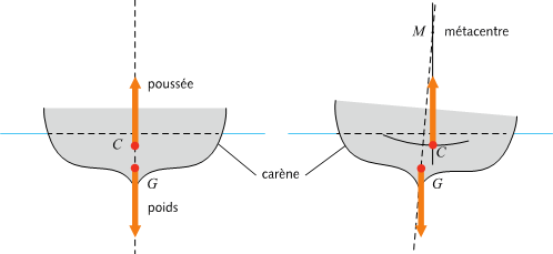
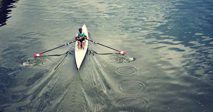
For a given submerged volume and for a given weight, the flotation area can be more or less wide. When it is not very wide, as in the case of a long pirogue, during a roll inclination, all the points of this surface are close to the axis, so that, since the lever arm is short, the moment of the return forces due to the pressure of the water on the edges of the hull remains very moderate. On the contrary, when the waterline is very wide, as in the case of Figure 2, the return torque can be very high, because the hull finds an increased thrust quite far from the side where the vessel is leaning, and a decreased thrust on the other side. In other words, the centre of thrust shifts quite strongly from the side where the vessel is leaning, making the righting torque lever arm important.
This results in the existence of a point that has no equivalent in the case of submarines, called the metacenter M, located at the I/V distance above the thrust centre C on the (vertical) thrust action line. In this expression, I refers to the quadratic moment of the floating surface [3] with respect to its axis of symmetry. When the vessel is subjected to small inclinations, the metacenter M remains fixed and point C describes an arc of a circle of centre M and radius I/V. The stability condition requires that G be below M, not C. The difference from the submarine case is significant: the ship can be stable when G is above C, provided the metacenter is high enough. Under these conditions, a submarine would be unstable. This requires that, all other things being equal, the width l is quite large.
One way to obtain high values of the I/V metacentric radius, in order to guarantee the stability of the vessel, is to provide it with a double hull, none of which is close to the axis. So, since most of the flotation surface is far from the axis of symmetry, the metacentric radius can become very large. This is the principle of catamarans. Trimarans have a fairly large main hull around the axis, designed to carry the equipment necessary for navigation, masts, sails and ropes, but also to shelter the crew, flanked by two very light secondary hulls at a certain distance on each side. At equilibrium, only the central hull is partially submerged, but a moderate list is sufficient to bring one of the lateral hulls into contact with the water, which thus finds an additional support, systematically stabilizing. The righting torque due to this additional lateral thrust can be high due to the length of the lever arm. The trimaran therefore represents an intermediate formula between the monohull vessel and the catamaran, which has the advantage of becoming very stable at steep inclinations.
3. The bearing capacity explained by the balance of the pressure forces
What about these flying objects such as planes and gliders subjected to a negligible Archimedes thrust compared to their weight since they are much heavier than air? The force that allows them to fly away and then fly at a fixed altitude, called lift, is still the result of the pressure forces on their periphery. The first novelty lies in the speed of these objects: planes stopped at airports cannot take off [4], they only take off while driving and after exceeding a certain speed.
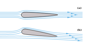
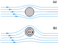
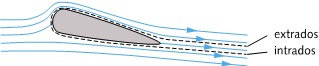
On the other hand, when the wing has a non-zero incidence, the symmetry is broken as shown in Figure 3b : the current lines tighten over the wing and move away below. Since the flow between two power lines must remain constant, the speed is all the greater as the power lines tighten. The air velocity is therefore lower along the lower surface than along the upper surface. However, to slow down the fluid particles that pass along the intrados in this way, resistance must be exerted on them. This resistance to their advancement is produced by an overpressure that takes place along the bottom surface and slows down the air locally by pushing it down. As a result, the pressure along the underside of the wing prevails over the pressure on the other side, and the balance of these pressures over the entire surface of the wing shows a non-zero vertical force. The wing is then subjected to a lift [5] related to the wing speed and its incidence.
In the case of an aircraft wing, the incidence is imposed by the pilot who, to take off, while the aircraft is already operating at a sufficient speed, turns the rear flaps down. Even if it does not modify the incidence of the entire wing, the pilot thus destroys the symmetry between the lower and upper surfaces, and this is what allows the lift to develop and to be able to overcome the weight. Conversely, to reduce the altitude before landing, the pilot reduces the incidence by raising the aft flaps to reduce or even negatively affect lift and add weight. In the case of a bird, it is the animal that makes the muscular effort necessary for the incidence and lift to appear.
The fact that the wing has a certain thickness reduces the effectiveness of this mechanism, but without compromising its principle. In aeronautics, we talk about the fineness of a wing to describe its slimness. The sails of a boat are good examples of thin wings. They are also curved by the wind that inflates them, which further accentuates the asymmetry and reinforces the pressure balance, a kind of horizontal lift transmitted to the boat by the mast. The combination of this lift on the sail and those exerted by the water on the rudder – another thin wing – and possibly on the keel – a third thin wing – even allows sailing in headwinds. The rear spoiler of competition cars is also designed to be subjected to lift, but negative lift, i.e. directed towards the ground like weight, in order to increase the vehicle’s handling.
4. The lift explained by the presence of a tourbillon
Now imagine that it is not the entire cylinder that rotates, but only a film layer, a kind of skin plated on its contour. For the flow of the ambient fluid, which only feels this skin, the result is the same. The cylinder with this movable skin is subjected to a lift whose sign depends on the direction of rotation of the skin.
A vortex therefore necessarily appears around the wing during takeoff. However, initially, no eddies were present. And this quantity is invariant over short periods of time in relation to the characteristic time of viscous friction. Another vortex, of the opposite direction and of the same intensity as the one that generates the lift, is therefore also created, but it does not surround the wing and we will see that it does not follow the plane and remains at the starting point.
5. The lift on a finite wing span
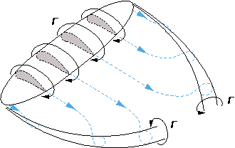
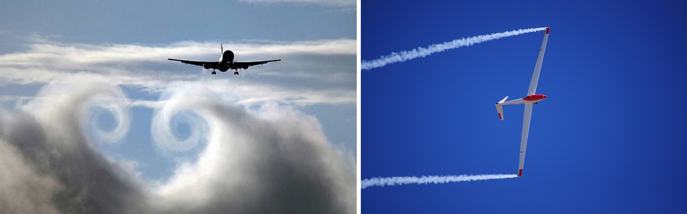
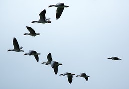
The V-shaped formation of migratory bird groups (Figure 8) is explained by the fact that each of them, except the first one, is placed in the upward current of the marginal eddy of the one before it. This saves him some of the effort needed to maintain his altitude. Any object or animal subjected to lift (plane, glider, bird or sail) is therefore associated with the formation of a very large vortex structure, in the form of a long tube closed on itself. This structure is regularly extended throughout the flight. Its intensity is related to the lift and its energy is taken from the energy supplied to these objects or expended by these birds.
Balls and balloons are examples of very small flying objects. The lift linked to the existence of a tourbillon makes it possible to explain their sometimes surprising trajectories, such as those of tennis or ping-pong balls, more or less curved by the movement of the racket. When the racket brushes the ball over it, the trajectory is strongly curved upwards. The ball is called lifted (from the English word lift which refers to lift); it is called cut or sliced (from the English word slice) when the racket brushes the ball from below. Another example is the curved trajectory in the horizontal plane of the football which, starting from the corner point, enters directly into the goalkeeper’s cage.

References and notes
Cover photo. Gliding flight of a griffon vulture illustrating the existence of a lift capable of compensating for its weight. [Source: Diverticimes]
[1] Archimedes, born in Syracuse around 287 BC and killed during the siege of this city in 212 BC, is one of the great scientists of Greek antiquity. His main discoveries concern statics and hydrostatics. Two of them still bear his name: Archimedes’ push and Archimedes’ screw.
[2] The centre of gravity of a volume is its centre of mass, or barycentre, in the event that it is filled with a homogeneous medium. The centre of gravity of a surface is defined in the same way, but in two dimensions.
[3] Any flat surface has two main orthogonal axes passing through its centre of gravity. In the case of a ship’s waterline, it is the axis of symmetry from bow to stern and the perpendicular axis. The quadratic moment with respect to each of these axes is generally expressed by an integral; it is often referred to as the moment of inertia. In the particular case of a rectangle with a long side L and a short side l, the expression of the quadratic moment with respect to the major axis is Ll3/12. In the case of a surface vessel, if the volume of the hull can be approached by Llh, where h is proportional to the draught, the metacentric radius is expressed as MC = l2/12 h.
[4] The flight of helicopters, birds and insects is due to the movement of their blades or wings, rotation for the former, rapid beating for the latter, which is a major difference compared to aircraft, whose wings remain stationary. The vertical take-off of some fighter aircraft is the result of another thrust from the jet from the engines.
[5] The theory of this lift, due to fluid mechanics Martin Wilhelm Kutta, German (1867-1944), and Nikolai Joukowsky, Russian (1847-1921), leads to the Kutta-Joukowsky formula for lift: P = ρVΓ, where ρ designates the density of the fluid, V its velocity in the distance and Γ the velocity circulation over the closed wing contour.
[6] The vortex intensity is the flow of the vortex vector (rotational velocity) through the right section of the wing. This value is equal to the velocity circulation on the wing contour, introduced in note[5] and noted Γ.
[7] This average velocity on the wing contour is proportional to a significant magnitude: the velocity circulation on this closed contour Γ, which is also equal to the intensity of the vortex.
[8] Care should be taken not to confuse these long cloud tubes, possibly present on the axis of the marginal eddies, with the large trails clearly visible in the wake of jet aircraft. The latter are due to the condensation of the large quantity of water vapour resulting from combustion and ejected by the nozzle downstream of the reactors. These aerial signatures of a jet plane passing through are always visible, even in a strong high and in dry air.
[9] In marine vocabulary, any section of the hull perpendicular to the major axis is called a torque and the largest of these is called the master torque.
The Encyclopedia of the Environment by the Association des Encyclopédies de l'Environnement et de l'Énergie (www.a3e.fr), contractually linked to the University of Grenoble Alpes and Grenoble INP, and sponsored by the French Academy of Sciences.
To cite this article: MOREAU René (January 5, 2025), Archimedes’ thrust and lift, Encyclopedia of the Environment, Accessed July 29, 2026 [online ISSN 2555-0950] url : https://www.encyclopedie-environnement.org/en/physics/archimedes-thrust-and-lift-2/.
The articles in the Encyclopedia of the Environment are made available under the terms of the Creative Commons BY-NC-SA license, which authorizes reproduction subject to: citing the source, not making commercial use of them, sharing identical initial conditions, reproducing at each reuse or distribution the mention of this Creative Commons BY-NC-SA license.