阿基米德的浮力和升力

Encyclopedie environnement - Poussée d'Archimède portance - archimede's weight and thrust

  航行于海洋的巨轮依靠阿基米德浮力(Archimedes’ thrust)来抵消重力,但是为什么他们能够如此稳定,在波涛汹涌的海面上也不会侧翻?天空之上,鸟类、飞机和滑翔机都比空气重得多,却似乎格外擅长飞行,比如封面图片中翱翔的雄鹰,它们的运动产生了一种能够抵消自身重量的力,称为升力(Lift)。

1. 回顾重力和阿基米德浮力

  一块石头,一旦被释放,就会因为重力落到地面。当地面给予它支撑,提供一个与重力刚好相反的力时,下落就会停止,这个力被称为地面对石头的反作用力(延伸阅读:《动力学定律》),于是石头又恢复了受力平衡。

  浸没在流体(例如空气、水)中的物体,表面会受到压强作用。在静止的状态下,压强的总效应刚好和被排开流体的重力相等,方向相反,被称为阿基米德浮力[1]。在空气中释放石头这一例子里,由于空气的密度大约只有石头的三千分之一,空气提供的浮力远比石头的重力要小。因此,根据基本的动力学原理,被释放的石头会迅速加速。气球则比石头下落得慢,如果充入诸如氦气、氢气这类比空气轻的气体,气球甚至还会上升。石头在水中也会下沉,但比在空中下落要慢得多。下沉之初,石头下落比在空气中慢,主要是因为石头与水的密度只相差3倍,尽管阿基米德浮力仍无法抵消重力,但两者的差别不像空气中那么大。随后,石头下落速度显著时,石头还会受到水的阻碍作用,这种阻碍被称为流体阻力,它大到足以让石头停止加速,并限制石头的最大下落速度。

2. 舰艇和潜水艇的稳定性

环境百科全书-阿基米德的浮力和升力-潜艇的平衡与稳定
图1. 潜艇的平衡与稳定。箭头分别表示潜艇处于(a)平衡,(b)向右倾斜,(c)即将侧翻时的重力和阿基米德浮力。[来源: © 法国EDP Sciences出版社, 法国格勒诺布尔(Grenoble)科学学院]

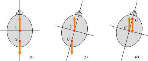
  潜艇和舰船可以在自身重力和阿基米德浮力之间保持平衡。但是这种浮力在波涛汹涌的海洋中是平衡的吗?让我们只考虑一种最危险的扰动——翻转,为了避开自由面,我们不妨想象潜艇处于下潜状态。潜艇可以简化为筒状,它的横截面形状接近椭圆,如图1所示。被潜艇排开的流体的重心在点C[2],它被称为浮心,是阿基米德浮力的作用点。而潜艇同样有个重心在点G,是潜艇重力的作用点,点G的位置取决于潜艇内的质量分布,因此潜艇重心的位置是可以改变的。首先,如图1a,在平衡状态下,点CG在同一条垂线上;然后让我们想象潜艇发生一个微小的倾斜,如图1b所示,如果GC下面,这对平行但不在一条线上的力产生的力矩会倾向于让潜艇回到稳态。如果GC的上面,如图1c,力矩将会倾向于让潜艇更快地倾斜。因此让潜艇稳定的条件就很清楚了:给潜艇配重时,必须确保GC的下面,这是个相对困难的要求。

  对于同时浸没在空气和水两种流体中的舰船来说,情况则有些不同。有人可能会认为空气并不重要,因为它的重量只有水的千分之一。的确,空气产生的浮力相对于水来说可以忽略,但是完全忽视空气并不可取,因为它会通过自由面起作用。船在水下的部分由船体本身和被排开水的自由面决定,被称为浮面,被浸没的船体和浮面共同决定了浸没体积。我们把阿基米德浮力分为两部分,一部分作用于左舷侧另一部分作用于右舷侧。船只的任何倾斜都会打破两者的对称性,让浮力的方向趋向于恢复船只平衡,这就是船和潜艇的不同之处。

环境百科全书-阿基米德的浮力和升力-横稳心位置和船稳定
图2. 横稳心M位于重心G的正上方时,船只是稳定的。在摆动的过程中,浮心C将在半径为MC =  的圆弧上移动。[来源: © 法国EDP Sciences出版社, 法国格勒诺布尔(Grenoble)科学学院]

  对于给定的浸没体积和重量,水线面区域应当或多或少宽一些。当水线面不是很宽时,比如一条细长的独木舟,在发生倾斜时,该面的所有点都离对称轴很近,因此力臂很短,船体表面的水压产生的恢复力矩在倾斜过程中改变不大。相反,当水线面很宽,如图2所示,恢复力矩可以变得非常大,因为船体在向下倾斜吃水一侧(图中对称轴右侧)的浮力有了大幅度的增加,而另一侧的浮力减小。换句话说,浮心向着船体倾斜的方向大幅转移,导致恢复力矩的力臂变大了。

  船只的这种特点使我们不得不引入横稳心M,它位于浮心所在垂线向上的距离处,其中I表示船只水线面相对于其对称轴的二阶矩[3],且M在潜艇的模型里没有对应的概念。当船只发生微小的倾斜,横稳心M将保持固定不动,点C将沿着M为圆心、I/V为半径的圆弧移动,如果希望船能自发恢复平衡态,则需要满足条件:重心G在横稳心M而不是浮心C的下方。与潜艇不同的是:只要横稳心足够高,船在重心G高于浮心C时依旧可以保持稳定。在其他条件相同时,水线面宽度l足够大,船只就越稳定。

  为了确保船体的稳定性,其中一种增大横稳心半径(Metacentric Radius)I/V的途径是采用双体(Double Hull)结构,两船体都远离对称轴。这样一来,由于大部分水线面都远离对称轴,稳心半径就可以变得很大,这就是双体船(Catamaran)的原理。三体船(Trimaran)在对称轴周围有相当大的主船体,用来携带桅杆、帆和缆绳等航海设备,同时也是船员们的避难所,两侧各有相隔一定距离的轻型辅助船体。在平衡状态时,只有主船部分吃水,若存在适度的倾斜就会让其中一侧的辅助船体与水面接触,从而获得额外的支撑,进而保持整体的稳定。由于辅助船体提供的浮力力臂很长,所以产生的恢复力矩可以很大。因此三体船能够在很严重倾斜下依旧保持稳定,是单体船和双体船的折中方案。

3. 用压强差解释飞行器的升力

  诸如飞机、滑翔机这样的飞行物比空气重得多,它们受到的阿基米德浮力与其重量相比可以忽略,它们又是如何工作的呢?让它们起飞并在一个固定高度飞行的力被称为升力,它同样也是压强作用在物体表面的结果。这些飞行物的新奇之处首先在于速度:飞机不能在机场停泊的时候直接起飞[4],只有在向前推进并达到一定速度后才能起飞。

环境百科全书-阿基米德的浮力和升力-对称机翼
图3. 在均匀风速中的无限翼展的对称机翼,(a)零迎角,(b)非零迎角。[来源: ©   法国EDP Sciences出版社, 法国格勒诺布尔(Grenoble)科学学院]

  为了理解升力的来源,我们首先来考虑一种极端简化的模型,一根很薄且具有无限翼展的对称机翼。这样,它以速度V飞行的问题就变成了二维问题,如图3a所示。想象一个在飞机上的观测者,他相对机翼静止,看到外面的气流以速度V从前方流过。在机翼迎角为0时,从机翼上方通过的气流和下方通过的气流是等量的,机翼的上下表面的气压也是相等的,从而两者垂直方向上的合力为0,机翼没有受到任何升力。

  另一方面如图3b,当机翼的迎角不为0,对称性被打破,流线在机翼上方的密集程度高于机翼下方。由于两条流线之间的气体流量是恒定的,当流线变密集,气流速度也会变快。因此机翼下表面的空气流速比上表面要慢。然而,气流流经机翼头部时,必定受到其阻碍作用而减速。这种阻碍由机翼下表面产生的“高压”提供,它减慢了局部空气的流速,导致机翼下表面的压强超过了上表面,这种压强差的总体效应表现为不为0的垂直方向的力。机翼因此受到了一个与风速和迎角有关的升力[5]

  在实际起飞的过程中,机翼的迎角是由飞行员进行调整的,在飞行器达到足够大的速度后,飞行员将后缘襟翼调低以使飞机起飞。尽管这并不会改变整个机翼的迎角,但飞行员这么做同样可以打破机翼上下表面的对称性,从而提供了能够克服重力的升力。相反,为了在降落前减小飞行高度,需要减小升力甚至提供负的升力时,飞行员会通过抬升后缘襟翼来减小迎角。而鸟类会通过肌肉控制来增加迎角,产生升力。

  机翼本身的厚度会削弱上述机制的效果,但并不影响其基本原理。在航空领域,我们经常用机翼的“细长比”来描述它的薄厚,船帆就是一个很好的薄翼例子。船帆被风吹鼓而产生弯曲,这种弯曲不但增加了其不对称性,也打破了压强平衡,相当于在水平方向上产生了升力,它会借由桅杆作用到船上。风作用于船帆上的升力和水作用于舵(另一个薄翼)以及可能作用于船身(第三个薄翼)上的升力相结合,甚至可以让帆船逆风航行。赛车上安装的后扰流板被设计成产生负升力(指向地面)的结构,增大了赛车与地面的接触力,从而增加了车辆的可操控性。

4. 用环量解释升力

环境百科全书-阿基米德的浮力和升力-放置在左侧来流中的圆柱
图4. 放置在均匀风场中的圆柱(左侧来风),(a)不旋转的圆柱,(b)以角速度ω旋转的圆柱。[来源:© 法国EDP Sciences出版社, 法国格勒诺布尔(Grenoble)科学学院]

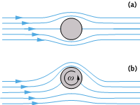
  除了用压强差来解释升力外,还有一种等效的解释,即环量升力理论。要引入这个概念,同时说明厚度不起主要作用,我们首先考虑一个横向放置在从左侧流来的气流中的无限长圆柱,图4展示了其纵剖面的流动。在(a)的情况下,圆柱上下表面的流动是完全对称的,压强的合力为0,也没有升力。而在情况(b)中,圆柱体开始绕其中心轴旋转,原本在圆柱两端相对的两个风速为0的点(驻点)同时向下移动,通过圆柱下方的流线发散,局部的压强增大。在圆柱的上表面则恰恰相反,流线变密集,局部速度变大,压强减小。于是,作用在整个圆柱表面的压强总效应就产生了一个与圆柱旋转有关的环量[6]以及来流速率成正比的升力。图4中的这一旋转圆柱的概念曾用于设计推动船只前进的旋转桅杆,但这一应用因为强风天气下收起旋转桅杆比减少船帆面积难得多而难以推行。

  现在想象一下,并非整个圆柱,而是只有贴在表面的一层蒙皮在旋转。对于周围流动的流体来说,它只能感受到圆柱表面旋转的蒙皮,因此得到的升力也是一样的。因此,只要气流中的圆柱具有旋转的表面,就能感受到升力,升力的方向取决于表面旋转的方向。

环境百科全书-阿基米德的浮力和升力-机翼尾迹
图5. 图1b的机翼上下表面附着的边界层在下游汇合,形成了机翼尾迹。[来源: ©法国EDP Sciences出版社, 法国格勒诺布尔(Grenoble)科学学院]

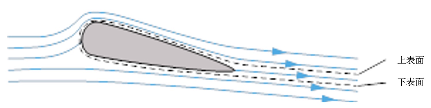
  但是飞行器的机翼不可能在表面包裹一层会动的蒙皮。事实上,起作用的并非机翼或者圆柱体表面附着点的速度,而是机翼表面一薄层外的流体速度,我们把这一薄层称为“边界层”(如图5虚线所示)。不过为了能够看清它,我们将它的厚度画得较为夸张。它从机翼的前缘开始沿着机翼的上下表面延伸,厚度逐渐变厚,在机翼后缘汇聚,形成机翼尾迹,由于存在迎角,边界层没有对称性。举个例子,如果机翼的前缘到后缘大约1m长,风速为100 m/s,即360 km/h,尽管边界层在机翼后缘处厚度达到最大,其厚度也不足1 mm。由于非对称性,对机翼边界层外边界做速度积分得到的环量并不为0[7],边界层就好比机翼表面附着的一层旋转运动的蒙皮一样。

  因此,在飞机起飞过程中,机翼表面附着的旋涡是不可避免的。但旋涡在起飞前是不存在的,它在很短时间建立起来并维持强度不变,这个时间要比粘黏性扩散的特征时间短得多。另一个方向相反且强度一致的旋涡也同时生成了,但这个旋涡并没有跟着飞机运动,而是留在了起飞前的位置,名为“起动涡”。

5. 有限翼展的升力

环境百科全书-阿基米德的浮力和升力-有限长机翼周围的流动
图6. 有限长机翼周围的流动图像,机翼上附着的涡和停留在机场的涡连接成一根大涡管,涡管强度为定值Γ。[来源: © 法国EDP Sciences出版社, 法国格勒诺布尔(Grenoble)科学学院]

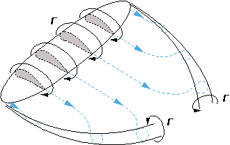
  我们离彻底理解升力产生的机制还差一步,即考虑真实机翼的有限翼展。图6定性展示了机翼周围的旋涡分布。流体在下翼面减速而形成的高压区主要发生在机翼的中段,在机翼的两端逐渐消失。在机翼的上表面也发生了类似的现象,但不是高压而是低压。这种效应沿着翼展变化,在机翼中段最明显,越靠近机翼尖端,效应越弱。机翼下表面巨大的高压把空气推向两端,而机翼上表面的低压有从两端向中间吸气的趋势。这说明在翼展的方向上,机翼下表面和上表面气流的横向速度是有差别的。这种横向的流动在机翼两端分别产生了蜷曲的旋涡(图6),形成了两个“翼尖涡”。这种结构与起飞时留下的起动涡、在机翼表面附着的旋涡构成了一个长而封闭的涡管。

环境百科全书-阿基米德的浮力和升力-翼尖涡
图7. 翼尖涡的图解。在左图中,一架大型飞机所产生的旋涡依靠飞机下方的云显现出来。在右图中,滑翔机机翼两端的旋涡因冷凝现象变得非常清晰。[来源:左图:DR.;右图:Pixabay网站]

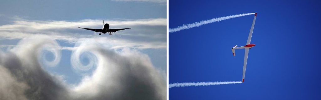
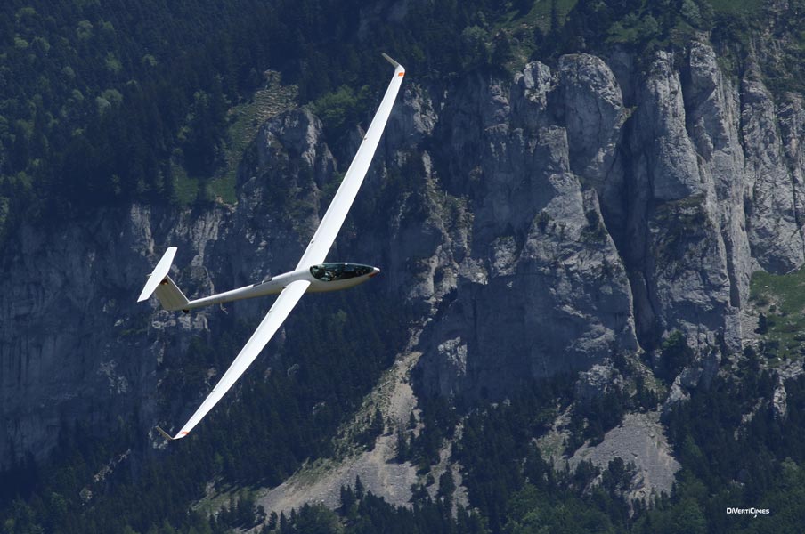
  图7左图中,机翼下方的云层被翼尖涡卷起,使得涡流清晰可见。要知道这些涡流的半径和单边机翼的长度是同一个数量级的。图7右图中,两条很细的云雾出现在滑翔机机翼两端[8],它们只发生在翼尖涡中心部分,靠近轴心,那里离心力产生的低压足以让空气中的水蒸气凝结。事实上,在上述条件下,湿度高到接近饱和的空气,因局部的绝热膨胀而冷却(参见热力学),这就是导致水蒸气凝结的原因。

环境百科全书-阿基米德的浮力和升力-候鸟排成V
图8. 排成V字形的候鸟。除了领头的那只,鸟群中的所有鸟都处于翼尖涡的上升气流中,以减少能耗。

  如图8所示,候鸟群呈V形列队飞行时,除领头的候鸟外,其他所有候鸟都处于前一只鸟的翼尖涡的上升气流中,这样就节省了部分它们为维持高度而耗费的能量。任何物体或动物(飞机、滑翔机、鸟或船帆)受到的升力都与这种涡结构(即封闭的管状结构)有关。这个结构在飞行过程中规则地延伸,它的强度与升力有关,能量则由飞行物自身提供。

环境百科全书-阿基米德的浮力和升力-热气流让滑翔机提升高度
图9. 在岩石坡附近,上升的热气流帮助滑翔机提升高度。[来源:DivertiCimes网站]

  大型猛禽在滑翔的时候(如封面图片)非常省力。较宽的翼展和翅膀结构使它们可以显著减少翅膀拍动的次数。滑翔机(如图7和图9)没有引擎,因此无法主动起飞,需要先由其它飞行器牵引到一定高度,然后与飞行器分离,飞行员会驾驶滑翔机寻找上升热气流,从而把它们带得更高,或至少保持当前的高度。其自身速度和迎角的确可以给它们提供升力,但也会受到局部垂直和水平方向气流的驱动。

  球和气球都是小型飞行物的例子。环量升力可以解释为何有时它们的运动轨迹出乎意料,比如网球或乒乓球的轨迹会或多或少因为击球方式而弯曲。如果球拍从球上表面擦过,球的轨迹是强烈向上弯曲的,这种球被称为上旋球(英文中用“lifted”一词);当球拍从下方擦过球时,则被称为下旋球(英文中用“cut”或“sliced”)。另一个例子是香蕉球,即足球在水平方向上轨迹的弯曲,运动员能够从角球点直接把球射进球门。

环境百科全书-阿基米德的浮力和升力-水翼帆船
图10. 阿伦·提波尔(Alain Thébault)为水手埃里克·塔博里(Eric Tabarly)将一艘18.24米长的“龙卷风三体帆船”改造成了水翼帆船。连接侧壳和水翼的细腿是钛制的,桅杆也是钛制的,高度为27米。2009年9月,这艘水翼船在500米的距离上以平均速度51.36节,最高速度55.5节(103km/h)打破了记录。[来源:左图:
卢多维奇·庞隆(Ludovic Peron)[CC BY-SA 2.5 (http://creativecommons.org/licenses/by-sa/2.5)], 维基共享百科;右图:托马斯·莱萨格(Thomas Lesage) [CC BY-SA 3.0 (http://creativecommons.org/licenses/by-sa/3.0)], 维基共享百科]

  水翼船是一种达到一定速度后能够浮出水面的船(见图10),这要归功于在水下相对较薄的水翼施加的升力。水翼位于船体下方,通过支柱与船体相接。通常,一套水翼不仅可提供升力,还可以增强船的稳定性。水翼最大的优势是通过最小化迎风面[9]来减少阻力。阅读拓展文章《运动物体受到的阻力》可知,阻力与迎风面积和速度的平方的乘积成正比。若整个船体和水翼的迎风面积为4.5 m2,当水翼船被水翼托举出水面后,迎风面积仅剩水翼的0.5m2,就意味着阻力减小到原来的九分之一。因此,由于阻力与迎风面积和速度的平方之乘积成正比,水翼船的航速将会比相同条件下没有水翼的船体航速快3倍。


参考资料及说明

封面图片:一只滑翔飞行的秃鹫展示了升力和重力的平衡. [来源:Diverticimes网站]

[1] 阿基米德,约公元前287年出生于西西里岛叙拉古,公元前212年在古罗马军队围城期间被杀。他是古希腊伟大的科学家,其主要发现为静力学和流体静力学。

[2] 对于均质介质,重心就是质心。二维的重心也同样可以定义。

[3] 任何平面都存在通过重心的两个正交的主轴。就船舶水线面而言,这两条轴就是从船头到船尾的对称轴和与其垂直的轴。这些轴的二阶矩通常被称为转动惯量,一般用积分表示。一个长为L、宽为l的矩形,相对于长轴的二阶矩为Ll3/12。对于水面的船只来说,如果船体的体积约为Llh,其中h与吃水深度成比例,横稳心半径表示为MC = l2/(12 h)。

[4] 直升机、鸟类和昆虫能飞行得益于它们桨叶或翅膀的运动,前者的旋转,后者的快速挥拍,都区别于飞机的固定式机翼。一些战斗机的垂直起飞是依靠发动机的垂直喷流推进的。

[5] 这个升力理论由德国流体力学家马丁·威廉·库塔(Martin Wilhelm Kutta,1867-1944)和俄国流体力学家尼古拉∙茹科夫斯基(Nikolai Joukowsky,1847-1921)提出,用库塔-茹科夫斯基(Kutta-Joukowsky)公式表示: P = ρVΓ, ρ是流体的密度,V是机翼运动速度,Γ是机翼表面的速度环量.

[6] 旋涡强度指通过给定面的涡量通量,大小等于等于速度环量,也记为Γ.

[7] 机翼轮廓线上的平均速度与这一闭合曲线上的速度环量Γ成正比,且Γ与涡流强度相等。

[8] 值得注意的是,不要把这两根长长的云雾(显示翼尖涡的涡核)与喷气式飞机尾流中的尾迹混淆起来。后者是燃烧产生的大量水蒸气经喷管喷出后冷凝而成。喷气式飞机的这个特征总是可见的,即使是在高空和干燥的空气中。

[9] 在海洋专业中,垂直于船体主轴的任何截面都称为迎风面,其中最大的称为主迎风面。


环境百科全书由环境和能源百科全书协会出版 (www.a3e.fr),该协会与格勒诺布尔阿尔卑斯大学和格勒诺布尔INP有合同关系,并由法国科学院赞助。

引用这篇文章: MOREAU René (2024年4月12日), 阿基米德的浮力和升力, 环境百科全书,咨询于 2024年7月27日 [在线ISSN 2555-0950]网址: https://www.encyclopedie-environnement.org/zh/physique-zh/archimedes-thrust-and-lift/.

环境百科全书中的文章是根据知识共享BY-NC-SA许可条款提供的,该许可授权复制的条件是:引用来源,不作商业使用,共享相同的初始条件,并且在每次重复使用或分发时复制知识共享BY-NC-SA许可声明。

Archimedes’ thrust and lift

Encyclopedie environnement - Poussée d'Archimède portance - archimede's weight and thrust

To compensate for their weight, the gigantic cargo ships that travel the oceans benefit from Archimedes’ thrust. But why are they so stable and never tip over, even when the sea is rough? By comparison, birds, planes and gliders, much heavier than air, seem to perform extraordinarily well when flying, like the majestic vulture in the cover image. We will see that it is their movement that generates a force, called lift, that can compensate for their weight.

1. A look back at Archimedes’ weight and thrust

As soon as it is released, the stone falls to the ground, attracted by its weight. Its fall stops when its support on the ground provides it with a force exactly opposite to its weight, which is called the reaction of this support (link to the article The laws of dynamics). The rock is back in balance.

Bodies immersed in a fluid medium, such as air or water, are subjected to pressures on their periphery, the overall effect of which at rest is reduced to Archimedes’ thrust [1], equal to and opposite to the weight of the fluid displaced. In the example of the stone released into the air, this thrust is much lower than its weight, since the density of the air is about 3000 times lower than that of a stone. The released rock therefore accelerates strongly, in accordance with the fundamental law of dynamics. On the other hand, a balloon falls more slowly than the rock and can even rise if it is inflated with a gas lighter than air, such as helium or hydrogen. In water, the stone also falls but much slower than in the air. At the beginning of its fall, this is due to the fact that Archimedes’ thrust is still unable to compensate for its weight, but the imbalance of the two forces is moderate because the density of the water is only 3 times lower than that of a stone. Then, when its falling speed becomes significant, the penetration of the stone into the water encounters a resistance, called drag, sufficient to stop its acceleration and impose a limit on its falling speed (link to the article Resistance to advancing, or drag).

2. Stability of submarines and surface vessels

Encyclopedie environnement - Poussée d'Archimède portance - Stabilité de l’équilibre d’un sous-marin - stability of submarine's equilibrium - archimede's weight and thrust
Figure 1. Stability of a submarine’s equilibrium. The arrows represent Archimedes’ weight and thrust, a) in equilibrium position, b) when the torque is in the direction of a righting, c) when it is in the direction of a capsizing. [Source: © EDP Sciences, Grenoble sciences]
Submarines and ships can be in balance between their weight and Archimedes’ thrust. But is this balance stable in rough seas? Let us limit ourselves to considering only the most dangerous disturbance, rolling, and start by eliminating the free surface by imagining the case of a submarine diving. It is a kind of tube, whose straight section has a shape similar to that of an ellipse, shown in Figure 1. Archimedes’ thrust applies to point C, the centre of gravity of the displaced fluid volume [2], which is called the centre of thrust. The submarine’s mass also has a centre of gravity G, point of application of the weight, whose position depends on the stowage of the masses that make up this vehicle. The position of the centre of gravity can therefore vary. In equilibrium, points C and G are aligned on the same vertical. Let’s imagine a small roll inclination. Figure 1 immediately shows that, if G is below C, the torque formed by these two non-aligned but parallel forces tends to bring the submarine back to equilibrium. If G is above C, the torque tends to accentuate the imbalance. The stability condition of the submarine is therefore clear: it is necessary to give the various masses that make up this submersible positions such that G is below C. This is a relatively severe condition.

The situation is different for a surface vessel immersed in a combination of two fluids: water and air. One might think that air doesn’t count because it is almost a thousand times lighter than water. What is true is that the thrust of air is negligible compared to that of water. But it would be wrong to completely forget the air, which comes into play through the existence of the free surface. The submerged part of the boat is limited by the hull and by the portion of free surface removed by the presence of the ship, known as the flotation surface. Together, the hull and flotation surface limit the submerged volume V. Let us distinguish the two parts of Archimedes’ thrust, the one on the port side and the one on the starboard side. Any inclination of the vessel destroys the symmetry of these two pushes, in a direction that tends to restore the balance of the vessel. This is what distinguishes the case of a surface ship from that of the submarine.

Encyclopedie environnement - Poussée d'Archimède portance - Stabilité de l’équilibre d’un navire - archimede's weight and thrust - stability ship's equilibrium
Figure 2. Stability of a ship’s equilibrium when the metacenter M is located above the centre of gravity G. During oscillations the centre of thrust C moves over the arc of the circle with radius MC = I/V. |Source: © EDP Sciences, Grenoble sciences]

For a given submerged volume and for a given weight, the flotation area can be more or less wide. When it is not very wide, as in the case of a long pirogue, during a roll inclination, all the points of this surface are close to the axis, so that, since the lever arm is short, the moment of the return forces due to the pressure of the water on the edges of the hull remains very moderate. On the contrary, when the waterline is very wide, as in the case of Figure 2, the return torque can be very high, because the hull finds an increased thrust quite far from the side where the vessel is leaning, and a decreased thrust on the other side. In other words, the centre of thrust shifts quite strongly from the side where the vessel is leaning, making the righting torque lever arm important.

This results in the existence of a point that has no equivalent in the case of submarines, called the metacenter M, located at the I/V distance above the thrust centre C on the (vertical) thrust action line. In this expression, I refers to the quadratic moment of the floating surface [3] with respect to its axis of symmetry. When the vessel is subjected to small inclinations, the metacenter M remains fixed and point C describes an arc of a circle of centre M and radius I/V. The stability condition requires that G be below M, not C. The difference from the submarine case is significant: the ship can be stable when G is above C, provided the metacenter is high enough. Under these conditions, a submarine would be unstable. This requires that, all other things being equal, the width l is quite large.

One way to obtain high values of the I/V metacentric radius, in order to guarantee the stability of the vessel, is to provide it with a double hull, none of which is close to the axis. So, since most of the flotation surface is far from the axis of symmetry, the metacentric radius can become very large. This is the principle of catamarans. Trimarans have a fairly large main hull around the axis, designed to carry the equipment necessary for navigation, masts, sails and ropes, but also to shelter the crew, flanked by two very light secondary hulls at a certain distance on each side. At equilibrium, only the central hull is partially submerged, but a moderate list is sufficient to bring one of the lateral hulls into contact with the water, which thus finds an additional support, systematically stabilizing. The righting torque due to this additional lateral thrust can be high due to the length of the lever arm. The trimaran therefore represents an intermediate formula between the monohull vessel and the catamaran, which has the advantage of becoming very stable at steep inclinations.

3. The bearing capacity explained by the balance of the pressure forces

What about these flying objects such as planes and gliders subjected to a negligible Archimedes thrust compared to their weight since they are much heavier than air? The force that allows them to fly away and then fly at a fixed altitude, called lift, is still the result of the pressure forces on their periphery. The first novelty lies in the speed of these objects: planes stopped at airports cannot take off [4], they only take off while driving and after exceeding a certain speed.

Encyclopedie environnement - Poussée d'Archimède portance - Aile symétrique d’envergure infinie dans un vent uniforme - archimede's weight and thrust
Figure 3. Symmetric wing of infinite wingspan in a uniform wind from the left, a) with zero incidence, b) with non-zero incidence. [Source: © EDP Sciences, Grenoble sciences]
To understand the origin of this lift, let us first place ourselves in a simplified case to the extreme, by imagining a thin, symmetrical wing, and of infinite span. The flight of this wing at a speed of V becomes a two-dimensional phenomenon, as shown in Figure 3a. Imagine an observer in solidarity with this wing, who, like a passenger on an aircraft, sees the external fluid coming from upstream at speed V. In the case where the wing flies with zero incidence, the flow over the wing, or along the upper surface, and the flow under the wing, or along the lower surface, are identical. The pressures on the lower and upper surfaces are also symmetrical and the vertical component of their resultant can only be zero: this wing is not subjected to any lift.

On the other hand, when the wing has a non-zero incidence, the symmetry is broken as shown in Figure 3b : the current lines tighten over the wing and move away below. Since the flow between two power lines must remain constant, the speed is all the greater as the power lines tighten. The air velocity is therefore lower along the lower surface than along the upper surface. However, to slow down the fluid particles that pass along the intrados in this way, resistance must be exerted on them. This resistance to their advancement is produced by an overpressure that takes place along the bottom surface and slows down the air locally by pushing it down. As a result, the pressure along the underside of the wing prevails over the pressure on the other side, and the balance of these pressures over the entire surface of the wing shows a non-zero vertical force. The wing is then subjected to a lift [5] related to the wing speed and its incidence.

In the case of an aircraft wing, the incidence is imposed by the pilot who, to take off, while the aircraft is already operating at a sufficient speed, turns the rear flaps down. Even if it does not modify the incidence of the entire wing, the pilot thus destroys the symmetry between the lower and upper surfaces, and this is what allows the lift to develop and to be able to overcome the weight. Conversely, to reduce the altitude before landing, the pilot reduces the incidence by raising the aft flaps to reduce or even negatively affect lift and add weight. In the case of a bird, it is the animal that makes the muscular effort necessary for the incidence and lift to appear.

The fact that the wing has a certain thickness reduces the effectiveness of this mechanism, but without compromising its principle. In aeronautics, we talk about the fineness of a wing to describe its slimness. The sails of a boat are good examples of thin wings. They are also curved by the wind that inflates them, which further accentuates the asymmetry and reinforces the pressure balance, a kind of horizontal lift transmitted to the boat by the mast. The combination of this lift on the sail and those exerted by the water on the rudder – another thin wing – and possibly on the keel – a third thin wing – even allows sailing in headwinds. The rear spoiler of competition cars is also designed to be subjected to lift, but negative lift, i.e. directed towards the ground like weight, in order to increase the vehicle’s handling.

4. The lift explained by the presence of a tourbillon

Encyclopedie environnement - Poussée d'Archimède portance - Cylindre circulaire placé dans un vent uniforme - archimede's weight and thrust - circular cylinder
Figure 4. Circular cylinder placed in a uniform wind from the left, a) non-rotating cylinder, b) rotating cylinder with angular velocity ω [Source: © EDP Sciences, Grenoble sciences]
For the explanation of lift by the pressure balance, a strictly equivalent variant is often substituted, which consists in representing the lifting wing by a vortex. To introduce this notion, and to illustrate the fact that thickness does not play a primary role, let us first consider a circular cylinder of infinite length placed in a flow from the left (Figure 4). Under conditions (a), the symmetry between intrados and extrados is complete, the pressure balance is zero, as well as the lift. On the other hand, in case (b), where the cylinder rotates about its axis, the positions of the two opposite stopping points have both moved downwards, the current lines passing under the cylinder have diverged, the local velocity has decreased and the local pressure has increased. On the contrary, above the cylinder, the power lines tightened, the local speed increased and the pressure decreased. The pressure balance over the entire surface of the cylinder then leads to a non-zero and proportional lift both to the intensity of the vortex [6] schematized by the rotation of the cylinder and to the speed of the far flow. Rotating masts, similar to the cylinder in Figure 4, have been designed to propel ships, but their implementation has been hampered by the fact that in strong winds it is much more difficult to retract them than to reduce the sail area.

Now imagine that it is not the entire cylinder that rotates, but only a film layer, a kind of skin plated on its contour. For the flow of the ambient fluid, which only feels this skin, the result is the same. The cylinder with this movable skin is subjected to a lift whose sign depends on the direction of rotation of the skin.

Encyclopedie environnement - Poussée d'Archimède portance - Aile avec couches limites d’intrados et d’extrados - archimede's weight and thrust
Figure 5. Wing of Figure 1b, with the boundary layers of the lower and upper surface that meet downstream to form the wing wake, after undergoing different thickening. [Source: © EDP Sciences, Grenoble sciences]
But aircraft wings are not covered with moving skins. In fact, it is not the speed of the points belonging to the wall of the wing or cylinder that counts, but the speed of the fluid beyond a very thin fluid layer, called the boundary layer. This boundary layer around a wing is sketched in Figure 5, where its thickness is greatly exaggerated to make it visible. It begins at the leading edge, with a very thin initial thickness, gradually thickens on each side of the wing, without any symmetry due to the incidence, and the two layers of lower and upper surface eventually meet at the trailing edge to form the wing wake. For example, if the distance between the leading edge and the trailing edge of the wing is about one meter and the speed is about 100 m/s, or 360 km/h, the thickness of this boundary layer is less than 1 mm at the trailing edge, where it reaches its maximum. Due to this asymmetry, the average velocity taken over a closed contour passing at the outer boundary of the boundary layer [7] is non-zero, as if the surface of the entire wing and boundary layer were a moving skin rotating from the inside.

A vortex therefore necessarily appears around the wing during takeoff. However, initially, no eddies were present. And this quantity is invariant over short periods of time in relation to the characteristic time of viscous friction. Another vortex, of the opposite direction and of the same intensity as the one that generates the lift, is therefore also created, but it does not surround the wing and we will see that it does not follow the plane and remains at the starting point.

5. The lift on a finite wing span

Encyclopedie environnement - Poussée d'Archimède portance - écoulement autour d’une aile d’envergure finie - archimede's weight and thrust
Figure 6. Schematic flow pattern around a finite wingspan, with the presence of a vortex of intensity Γ, invariant throughout the large vortex tube that closes at the airport. [Source: © EDP Sciences, Grenoble sciences]
We still have one more step to take to fully understand the emergence of lift, from a wing of infinite span to a real wing of finite span. Figure 6 illustrates qualitatively, without respecting the length scales, the presence of the vortex along the wing. The slowing of the fluid particles and the overpressure on the underside of the wing pass through as much as possible in the middle of the wing and cancel each other out at its ends. A very similar variation appears on the upper surface, but with a different sign. This effect is therefore variable along the wingspan, maximum in the middle of the wing and lower and lower when going towards the tips. The large overpressure on the underside pushes the air from the centre to the ends, while the underpressure on the top surface draws the air from the ends to the centre. This shows a velocity component in the direction of the wingspan, from the middle of the wing to its tip on the lower surface and in the opposite direction on the upper surface. These transverse flows lead to the winding of a vortex web at each end of the wing (Figure 6), which forms two marginal vortices, also called tip vortices. This structure is closed by the vortex left at the starting point and by the vortex created around the wing, thus forming a long vortex tube closed on itself.

Encyclopedie environnement - Poussée d'Archimède portance - tourbillons marginaux - marginal eddies - archimede's weight and thrust
Figure 7. Illustration of marginal eddies at wingtips. On the left, the winding of these eddies generated by a large aircraft is made visible by the cloud below it. On the right, at the ends of the wings of a glider, these eddies are made visible by a condensation phenomenon located near their axis [Source: (left image) DR. (right image) Pixabay]
In the photograph on the left side of Figure 7, it is the presence of a cloud below the plane, drawn into these marginal eddies, that makes them visible. It should be noted that their diameter is of the same order of magnitude as the length of each wing. In the case of the glider on the right-hand side of Figure 7, two very thin clouds begin at the rear of the wing [8]. They occupy only the central part of the marginal eddies, in the immediate vicinity of their axis, where the vacuum due to centrifugal force is sufficient to generate local condensation of the water vapour present in the air. Indeed, under these conditions, the air that carries a fairly high humidity, close to saturation, is subjected to local cooling by adiabatic expansion (link to Thermodynamics). This is what causes the condensation of water vapour.

Encyclopedie environnement - Poussée d’Archimède portance - vol en V oiseaux migrateurs - archimede's weight and thrust
Figure 8. V-shaped formation of migratory birds. With the exception of the leader, all the birds in the group are placed in the updraft of the marginal eddies to minimize the effort required.

The V-shaped formation of migratory bird groups (Figure 8) is explained by the fact that each of them, except the first one, is placed in the upward current of the marginal eddy of the one before it. This saves him some of the effort needed to maintain his altitude. Any object or animal subjected to lift (plane, glider, bird or sail) is therefore associated with the formation of a very large vortex structure, in the form of a long tube closed on itself. This structure is regularly extended throughout the flight. Its intensity is related to the lift and its energy is taken from the energy supplied to these objects or expended by these birds.

Encyclopedie environnement - Poussée d’Archimède portance - Planeur - archimede's weight and thrust - glider
Figure 9. Glider in the vicinity of rocky slopes on which rising thermal winds can allow it to gain altitude. [Source: DivertiCimes]
The gliding flight of large birds of prey (cover image) is remarkably energy efficient. It is this efficiency, due to both the wingspan and configuration, that allows them to significantly limit their wing flapping. The gliders (Figures 7 and 9), without engines and therefore unable to take off, are first towed to altitude by an aircraft. There, detached from the aircraft, they are guided by the pilot who is looking for thermal updrafts that can carry them even higher, or at least maintain their altitude. Their own speed and incidence do give them lift, but they are also driven by local currents, both vertically and horizontally.

Balls and balloons are examples of very small flying objects. The lift linked to the existence of a tourbillon makes it possible to explain their sometimes surprising trajectories, such as those of tennis or ping-pong balls, more or less curved by the movement of the racket. When the racket brushes the ball over it, the trajectory is strongly curved upwards. The ball is called lifted (from the English word lift which refers to lift); it is called cut or sliced (from the English word slice) when the racket brushes the ball from below. Another example is the curved trajectory in the horizontal plane of the football which, starting from the corner point, enters directly into the goalkeeper’s cage.

Encyclopedie environnement - Poussée d’Archimède portance - voilier hydroptère Alain Thébault - archimede's weight and thrust - hydrofoil saiboat
Figure 10. Hydrofoil sailboat built by Alain Thébault for sailor Eric Tabarly from an 18.24 m long Tornado trimaran hull. The thin legs that connect the side shells to the wing are made of titanium, the height of the mast, also made of titanium, is 27 m. This hydrofoil broke the speed record over a distance of 500 m in September 2009: 51.36 knots, or 95.3 km/h, with a top speed of 55.5 knots, or 103 km/h. [Source: (left photo) By Ludovic Peron (Personal photo)[CC BY-SA 2.5 (http://creativecommons.org/licenses/by-sa/2.5)], via Wikimedia Commons. (right photo) By Thomas Lesage (Own work)[CC BY-SA 3.0 (http://creativecommons.org/licenses/by-sa/3.0)], via Wikimedia Commons]
Hydrofoils are boats whose hulls are able to emerge from the water when their speed exceeds a certain limit (Figure 10), thanks to the lift exerted on a relatively thin wing, which remains underwater. This wing is located under the hull, at the ends of the struts that connect it to the hull. In some cases it is a set of wings that provide this lift, which improves the stability of the hydrofoil. The great advantage of hydrofoils over ships is to reduce drag by minimizing master torque [9]. We will read in the article Progress resistance and drag (link) that this drag is proportional to the product of the area of the master torque by the square of the speed. Thus, instead of the total master torque of the entire hull and wing – for example 4.5 m2 -, when the hydrofoil is significantly reduced, say to 0.5 m2, which means that it can be divided by 9. So, since the drag is proportional to the product of this area by the square of the speed, the speed of the hydrofoil can be 3 times greater than that of a ship built on the same hull without the submerged wing.


References and notes

Cover photo. Gliding flight of a griffon vulture illustrating the existence of a lift capable of compensating for its weight. [Source: Diverticimes]

[1] Archimedes, born in Syracuse around 287 BC and killed during the siege of this city in 212 BC, is one of the great scientists of Greek antiquity. His main discoveries concern statics and hydrostatics. Two of them still bear his name: Archimedes’ push and Archimedes’ screw.

[2] The centre of gravity of a volume is its centre of mass, or barycentre, in the event that it is filled with a homogeneous medium. The centre of gravity of a surface is defined in the same way, but in two dimensions.

[3] Any flat surface has two main orthogonal axes passing through its centre of gravity. In the case of a ship’s waterline, it is the axis of symmetry from bow to stern and the perpendicular axis. The quadratic moment with respect to each of these axes is generally expressed by an integral; it is often referred to as the moment of inertia. In the particular case of a rectangle with a long side L and a short side l, the expression of the quadratic moment with respect to the major axis is Ll3/12. In the case of a surface vessel, if the volume of the hull can be approached by Llh, where h is proportional to the draught, the metacentric radius is expressed as MC = l2/12 h.

[4] The flight of helicopters, birds and insects is due to the movement of their blades or wings, rotation for the former, rapid beating for the latter, which is a major difference compared to aircraft, whose wings remain stationary. The vertical take-off of some fighter aircraft is the result of another thrust from the jet from the engines.

[5] The theory of this lift, due to fluid mechanics Martin Wilhelm Kutta, German (1867-1944), and Nikolai Joukowsky, Russian (1847-1921), leads to the Kutta-Joukowsky formula for lift: P = ρVΓ, where ρ designates the density of the fluid, V its velocity in the distance and Γ the velocity circulation over the closed wing contour.

[6] The vortex intensity is the flow of the vortex vector (rotational velocity) through the right section of the wing. This value is equal to the velocity circulation on the wing contour, introduced in note[5] and noted Γ.

[7] This average velocity on the wing contour is proportional to a significant magnitude: the velocity circulation on this closed contour Γ, which is also equal to the intensity of the vortex.

[8] Care should be taken not to confuse these long cloud tubes, possibly present on the axis of the marginal eddies, with the large trails clearly visible in the wake of jet aircraft. The latter are due to the condensation of the large quantity of water vapour resulting from combustion and ejected by the nozzle downstream of the reactors. These aerial signatures of a jet plane passing through are always visible, even in a strong high and in dry air.

[9] In marine vocabulary, any section of the hull perpendicular to the major axis is called a torque and the largest of these is called the master torque.


环境百科全书由环境和能源百科全书协会出版 (www.a3e.fr),该协会与格勒诺布尔阿尔卑斯大学和格勒诺布尔INP有合同关系,并由法国科学院赞助。

引用这篇文章: MOREAU René (2019年2月5日), Archimedes’ thrust and lift, 环境百科全书,咨询于 2024年7月27日 [在线ISSN 2555-0950]网址: https://www.encyclopedie-environnement.org/en/physics/archimedes-thrust-and-lift/.

环境百科全书中的文章是根据知识共享BY-NC-SA许可条款提供的,该许可授权复制的条件是:引用来源,不作商业使用,共享相同的初始条件,并且在每次重复使用或分发时复制知识共享BY-NC-SA许可声明。