

Why do earthquakes trigger catastrophic landslides?
PDF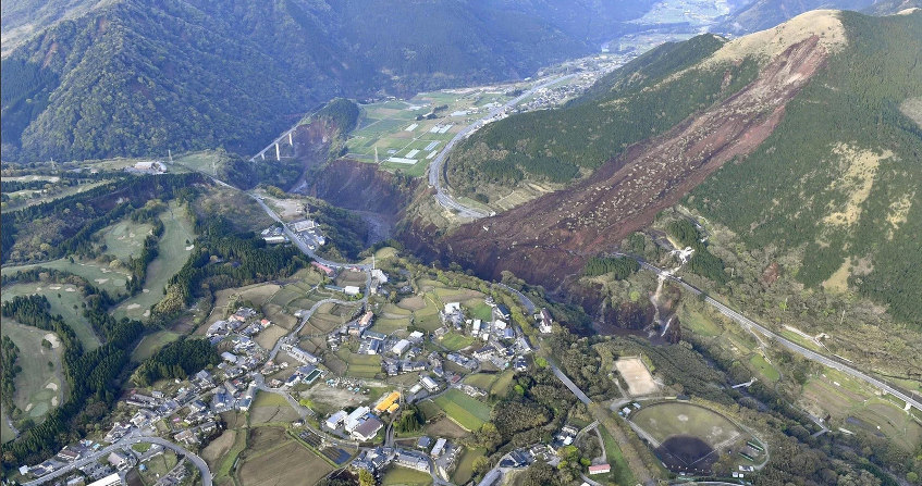
Can all earthquakes trigger ground movements? Each year, earthquakes are responsible for loss of life and damage to buildings and infrastructure. Long considered as a secondary effect of earthquakes, landslides triggered by earthquakes, mainly rock falls, disrupted soil slides and rock slides, mudflows and rock avalanches, can be responsible for a significant part of the damage associated with earthquakes [1]. During the twentieth century, nearly 80 earthquakes caused 100,000 to 1,000,000 ground movements that claimed the lives of several tens of thousands of people [2]
- 1. Can all earthquakes trigger ground movements?
- 2. What are the characteristics of these ground movements?
- 3. What is the impact of these movements on people and territories?
- 4. How do we explain these instabilities?
- 5. What methods can be used to assess slope stability in earthquakes?
- 6. What are the current challenges in research on earthquake-induced ground movements?
- 7. Messages to remember
1. Can all earthquakes trigger ground movements?
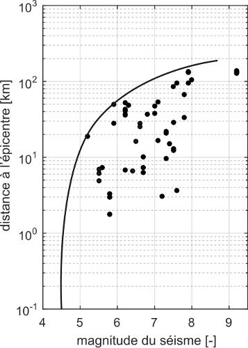
- 1st observation: Most instabilities are triggered by earthquakes of moderate to high magnitude [3], typically greater than 5 (Figure 1). However, this notion of “minimum magnitude” or magnitude threshold should be considered with caution because it does not take into account the state of stability of the slope before the earthquake. This state, often poorly known, is the result of the entire history of “loading” (earthquakes, heavy rainfall).
- 2nd observation: most of these ground movements do not occur beyond a certain distance from the source of the earthquake, which depends on the magnitude of the earthquake in question. The higher the magnitude of an earthquake, the more likely it is to trigger ground movements at a long distance from the epicentre (Figure 1) [5].
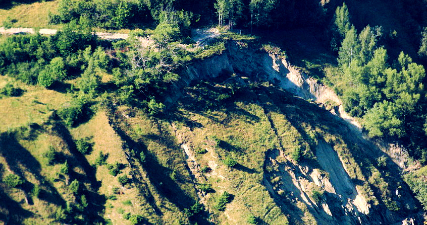
2. What are the characteristics of these ground movements?
The “intensity” of earthquake-initiated ground movements can be characterized by:
- The volume of materials moved by the movement;
- the mobility of these materials during movement;
- the area covered by the materials after the movement has stopped.
Keefer’s (1984) work has shown that this “intensity” depends on the magnitude of the earthquake under consideration: the higher the magnitude of the earthquake, the greater the “intensity” of the ground movements it may trigger.
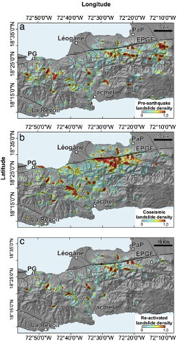
Some earthquakes can even reactivate old ground movements, as was the case during the earthquake of January 12, 2010 in Haiti: this earthquake triggered about 4500 ground movements up to a distance of 46 km from the epicenter. Of the 1273 landslides recorded as active before the 2010 earthquake, 572 were reactivated by the 2010 earthquake (Figure 2) [8].
3. What is the impact of these movements on people and territories?

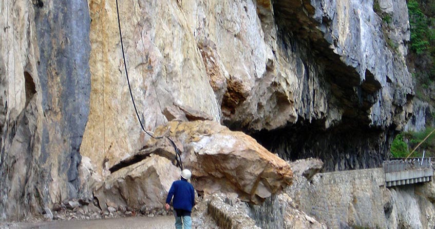
Earthquake-initiated ground movements can have two types of effects:
- direct effects: deaths resulting from the burial of buildings or the crushing of vehicles by debris from ground movements, damage / destruction of buildings, communication networks, etc.
- indirect effects: the degradation or obstruction of roads by debris from ground movements can hinder the delivery of aid to victims or their evacuation to health centres.
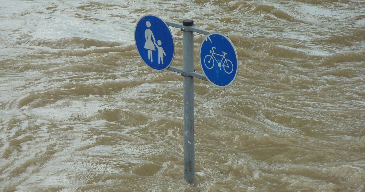
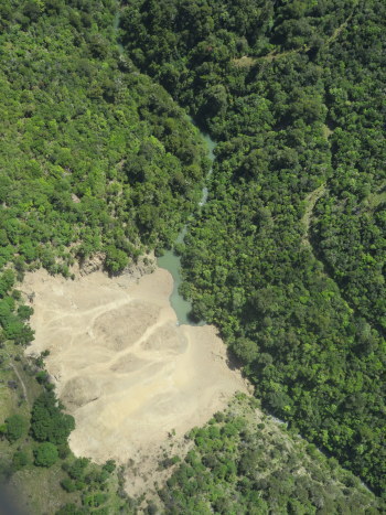
Sometimes debris from ground movements blocks the bed of rivers and forms natural dams. This leads to the formation of dam lakes upstream of ground movements. This type of phenomenon occurred in large numbers (several hundred) during the earthquake of May 12, 2008 in China. This animation [11] shows a slope before and after the onset of a ground movement by the 2008 earthquake.
- How can we ensure that these natural dams are properly maintained over time and thus avoid a disruption that could lead to catastrophic flooding of urban areas located near the sites
- How will the lakes formed upstream of the dams evolve, especially if heavy rainfall increases the water level in the reservoirs?
- Few scientific studies to date have anticipated what could happen in such circumstances.
4. How do we explain these instabilities?
To decide on the state of stability or not of a slope, one must compare:
- the driving forces that tend to destabilize the slope. These forces are caused by an earthquake, heavy rainfall.
- the resistant forces that oppose the movement. These forces are provided by the intrinsic characteristics of the materials, in particular their cohesion and internal friction angle, two parameters that reflect the failure criterion of soils according to Mohr Coulomb’s law [13].
During an earthquake, several phenomena can occur and contribute to the onset of instability.
4.1. Site effects
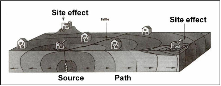
- A parameter related to the source of the earthquake. This parameter reflects the nature of the earthquake: failure mechanism at the focus of the earthquake, length of the fault, etc.
- A parameter related to the propagation of seismic waves between the source of the earthquake at depth and the sensors where surface movements are recorded: during this journey, the volume waves emitted at the source will undergo multiple transformations that depend on the properties of the environments crossed.
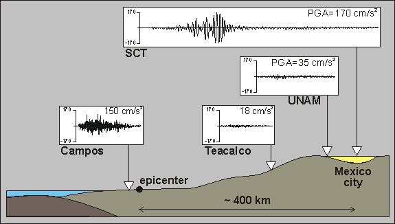
- A parameter related to the effect of local geological and topographical conditions (i.e. type of material under and near the sensor, terrain morphology) on seismic wave propagation and recorded surface movements. This parameter is called the site effect. Due to site effects, seismic movements vary from one point to another on the surface of a slope. When compared to the reference seismic movement measured near the slope of a rocky site (Campos station in Figure 6), it can be seen that movements in sedimentary basins (SCT station in Figure 6) or at the top of the slope generally have higher amplitudes and a longer duration. Field observations [14] and numerical modelling results [15] show that site effects most certainly contribute to the initiation of ground movements.
4.2. The decrease in the mechanical characteristics of materials
Repeated earthquakes on a slope lead to a deformation of the materials that make up the slope. This can lead to a decrease in the intrinsic characteristics of materials that tend to oppose movement and thus facilitate the development of an overall break in the slope.
4.3. The increase in pore pressures
When the compression waves emitted by earthquakes propagate in loosely compacted soils, they tend to compress the soils. When these soils are saturated with water, water occupies all the pores (or interstices) between the soil grains. In response to soil compression, the pressure of water in soil pores increases and water seeks to escape from the soil generally to the surface. However, when the earthquake is rapid, large enough or repeated over time in front of the time needed to drain the soil, water cannot escape from the soil. The higher the water pressure in the soil, the lower the mechanical strength of the soil and the more likely it is that the slope will break.
5. What methods can be used to assess slope stability in earthquakes?
When considering slope stability in earthquakes, two questions in particular should be addressed:
- can the slope be ruptured during an earthquake of given characteristics?
- if so, what are the characteristics of this failure, in particular how far can the slipped mass propagate and at what speed?
Few scientific studies to date have focused on the characterization of instability in terms of propagation speed and distance, given the complexity of the phenomena involved.
5.1. Slope characterization
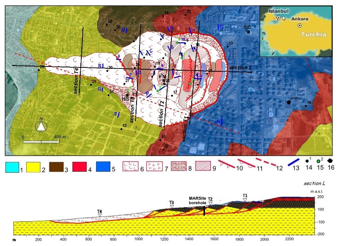
- an in-depth geological study whose objective is to define the geometry, stratigraphy, geological history of the site (Figure 7 [16]).
- a hydrogeological study to characterize water flows in soils, for example by means of piezometers that measure changes in groundwater levels in boreholes, since water is very often the driving force behind these movements.
- the characterisation of the mechanical behaviour of the materials making up the slopes by means of mechanical tests, most often carried out in the laboratory, the objective being in particular to define their shear strength, characterised by cohesion and the internal friction angle.
From the above parameters, calculation software can be used to determine whether a slope is stable or unstable, by comparing the driving forces that tend to destabilize the slope with the resistant forces that oppose movement. This defines the static safety coefficient of the slope. When this coefficient is greater than 1 (in the case of a slope in which the resistant forces are greater than the driving forces), the slope is stable. When it is less than 1, the slope is unstable. The closer this coefficient is to 1 (e.g. in the case of a slope that has suffered many earthquakes in the past), the more an earthquake, even of moderate magnitude, can trigger a rupture in the slope.
To analyze the stability of a slope during an earthquake, it is also necessary to characterize the potential earthquake(s): it is on this characterization that the different methods used to evaluate the stability of a slope during an earthquake are based.
5.2. Methods for analyzing slope stability in earthquakes
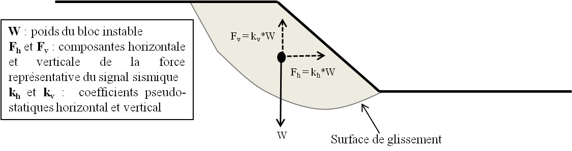
The simplest of these, Terzaghi’s pseudo-static method [17], consists in calculating the pseudo-static safety coefficient of the slope. In this method, the earthquake is represented by a constant and unique volume force, of modulus proportional to the weight of the unstable block. This force noted F is divided into a horizontal component Fh and a vertical component Fv (Figure 8). In practice, Fv is often neglected because the most damaging forces for slope stability are horizontal or shear forces. This method makes it possible to determine whether the slope is stable (pseudo-static safety coefficient greater than 1) or unstable (pseudo-static safety coefficient less than 1) during the earthquake.
Disadvantage of the method: This method does not provide information on the probability of slope failure or on the “intensity” of movements induced by the earthquake. It is therefore advisable to limit its use to a preliminary analysis of the stability of a slope during an earthquake, in an area where there are few human or material challenges.
Disadvantages of the method:
- This method does not take into account the internal deformations of the unstable mass during the earthquake (paragraph 4.2.). Its use is therefore reserved for the study of relatively superficial ground movements in rigid materials unlikely to deform during the earthquake.
- This method does not take into account the pore pressures that can develop in soils as a result of earthquakes (section 4.3.).
- This method does not take into account site effects (paragraph 4.1.).
6. What are the current challenges in research on earthquake-induced ground movements?
The study of earthquake-initiated ground movements is now the subject of much research aimed at improving relative knowledge:
- to the effects of water. According to current knowledge, the role of water in triggering ground movements during earthquakes is relatively unknown.
- to three-dimensional effects (or 3D effects). Due to the complexity of the phenomena, the stability of the slopes is often analysed in an approximate way by means of two-dimensional (2D) sections often oriented in the direction of propagation of instability. This approximation, justified in the case of anthropic slopes, is often unrealistic for natural slopes. Representing the slope in all its dimensions (3D) in a numerical calculation code makes it possible to take into account the direction of propagation of seismic waves and to study its impact on the stability of the slope.
- the prediction of earthquake-initiated ground movements. To organize disaster prevention, it is necessary to be able to predict where and when the next earthquake-induced ground movements will occur. This requires knowing at some point the state of stability of the slopes, a state that is often poorly known and has resulted from the entire history of “loading” on the slopes in the past. It also requires the ability to predict what type of earthquake is likely to affect a given site and when it may occur. Finally, this requires being able to quantify the “intensity” of the expected phenomena, i.e. to characterize both the volume of instabilities or the surface that could be covered by the deposits of this instability, the propagation speed of the unstable mass and its propagation distance. These are difficult parameters to assess because earthquake-initiated ground movements are complex and variable from one earthquake to another.
Field observations have also shown that earthquakes can also have long-term effects on slope stability: in the years following the 21 September 1999 earthquake in Taiwan, for example, there was an increase in the number of ground movements triggered by monsoon episodes [22]. The latter is explained by the fact that the earthquake weakened the slopes, making them more susceptible to instability during the subsequent episodes of heavy rainfall.
7. Messages to remember
- Earthquakes with a magnitude greater than 5 are likely to trigger ground movements that can be responsible for a significant proportion of the victims and the damage associated with earthquakes.
- There is a wide variety of ground movements triggered by earthquakes and these phenomena are generally very complex.
- Reducing the risk posed by this type of hazard requires a better understanding of the mechanisms that trigger ground movements on the one hand and the mechanisms that control the speed and distance of material propagation on the other.
References and notes
Cover image. A ground movement that occurred in the city of Minamiaso, Japan, following the April 2016 earthquakes. [Photo © Kyodo/Reuters via Flickr, Public domain.]
[1] Bird J.J. & Bommer J.J. (2004). Earthquake losses due to ground failure. Engineering Geology, 75 (2), p. 147-179. < https://doi.org/10.1016/j.enggeo.2004.05.006>.
[2] Keefer D.K. (1984). Landslides caused by earthquakes. Bulletin of the seismological society of America, 95, pp. 406-421.
[3] The magnitude is used in seismology to represent the seismic moment that measures the energy released by an earthquake. The more energy an earthquake has released, the higher its magnitude: a magnitude increase of 1 corresponds to a 30-fold increase in the energy released by the earthquake.
[4] Gishig V., Preisig G. & Eberhardt E. (2016). Numerical Investigation of Seismically Induced Rock Mass Fatigue as a Mechanism Contributing to the Progressive Failure of Deep-Seated Landslides. Rock Mechanics and Rock Engineering. 49: 2457. < https://doi.org/10.1007/s00603-015-0821-z>>.
[5] Dome J G., Bourdeau C., Lenti L., Martino S. & Pluta K. (2017). Mean landslide geometries inferred from a global database of earthquake- and non-earthquake-triggered landslides. Italian Journal of Engineering Geology and Environment, 2. https://doi.org/10.4408/IJEGE.2017-02.O-05.
[6] (https://www.ngdc.noaa.gov/hazardimages/picture/show/785)
[7] Lliboutry L. A. (1975). The Yungay disaster (Peru). Snow and Ice-Symposium-Neiges et Glaces. (Proceedings of the Moscow Symposium, August 1971; Proceedings of the Moscow Colloquium, August 1971): IAHS-AISH Publ. No. 104.
[8] Gorum T., van Westen C. J., Korup O., van der Meijde M., Fan X. & van der Meer F. D. (2013). Complex rupture mechanism and topography control symmetry of mass-wasting pattern, 2010 Haiti earthquake Geomorphology184, p. 127-138. < https://doi.org/10.1016/j.geomorph.2012.11.027>>.
[9] Petley D., Dunning S., Rosser N. & Kausar A.B. (2006). Incipient landslides in the Jhelum Valley, Pakistan following the 8th October 2005 earthquake. SAARC Workshop on Landslide Risk Management in South Asia.
[10] Yin, Y., Wang, F. & Sun, P. (2009). Landslide hazards triggered by the 2008 Wenchuan earthquake, Sichuan, China. Landslides 6, 139-151.
[11] Contains modified Copernicus Sentinel data {{{year}}}} [CC BY 3.0 (https://creativecommons.org/licenses/by/3.0) or Attribution], via Wikimedia Commons
[12] GeoNet, Geological hazard information for New Zealand
[13] Mohr Coulomb’s law: this mathematical law is used in geotechnics to describe in an approximate way the behaviour of most long-term soils subjected to shear stresses (known as shear failure). This law is characterized by two parameters: cohesion, which defines the shear strength of the soil under zero normal stress, and the internal friction angle, which corresponds to the angle naturally formed by a soil placed in a pile, with respect to the horizontal.
[14] Miller P., Hovius N. & Haines J.A. (2008). Topographic site effects and the location of earthquake induced landslides. Earth and Planetary Science Letters. 275, 221–232.
[15] Bozzano F., Lenti L., Martino M., Paciello A. & Scarascia Mugnozza G. (2008). Self-excitation process due to local seismicamplification responsible for the reactivation of the Salcito landslide (Italy) on 31 October 2002. Journal of Geophysical Research 113, B10312. <https://doi.org/10.1029/2007JB005309>>.
[16] Bourdeau C., Lenti L., Martino S., Oguz O., Yalcinkaya E., Bigarre P. & Coccia A S. (2017). Comprehensive analysis of the local seismic response in the complex Büyükçekmece landslide area (Turkey) by engineering-geological and numerical modelling. Engineering Geology 218, 90-106. < http://dx.doi.org/10.1016/j.enggeo.2017.01.005>.
[17] Terzaghi K. (1950). Mechanism of Landslides. Geological Society of America, Harvard University Press, 41 p.
[18] Newmark N.M. (1965). Effects of earthquakes on dams and embankments. Geotechnics 15, 139-160.
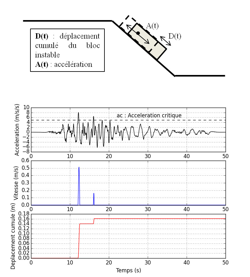
[19] Accelerogram: A signal giving the acceleration of the ground as a function of time is called an “accelerogram”.
[20] Cundall P.A. & HART R.D. (1992). Numerical modelling of discontinua. Eng. Comp. 9:101-113
[21] Itasca. (2011). UDEC-Universal Distinct Element Code, Version 5.0. User’s Manual. Itasca Consulting Group, Inc. in Minneapolis
[22] Hovius N., Meunier P., Lin C.-W., Hongey C., Chen Y.-G., Dadson S., Horng M.-J. & Lines M. (2011). Prolonged seismically induced erosion and the mass balance of a large earthquake. Earth and Planetary Science Letters 304, 347-355
The Encyclopedia of the Environment by the Association des Encyclopédies de l'Environnement et de l'Énergie (www.a3e.fr), contractually linked to the University of Grenoble Alpes and Grenoble INP, and sponsored by the French Academy of Sciences.
To cite this article: BOURDEAU Céline (January 5, 2025), Why do earthquakes trigger catastrophic landslides?, Encyclopedia of the Environment, Accessed July 15, 2026 [online ISSN 2555-0950] url : https://www.encyclopedie-environnement.org/en/soil/why-earthquakes-trigger-catastrophic-landslides/.
The articles in the Encyclopedia of the Environment are made available under the terms of the Creative Commons BY-NC-SA license, which authorizes reproduction subject to: citing the source, not making commercial use of them, sharing identical initial conditions, reproducing at each reuse or distribution the mention of this Creative Commons BY-NC-SA license.