Soil reinforcement: techniques that have become essential

PDF
Encyclopédie environnement - renforcement des sols - couverture

Thanks to innovative techniques, it is now possible to build on all types of floors. From simple structures to architectural feats, the know-how of engineers is mobilized to analyze, study, reinforce and consolidate soils. The geotechnician probes and determines the characteristics of the soil in order to design, within design offices, the foundations of the structures. Soil reinforcement, although generally invisible, is the cornerstone of any structure built on soil with poor mechanical characteristics. Current technological developments in soil reinforcement are moving towards more economical and environmentally friendly technical solutions.

The need for poor quality land development is increasingly necessary, given the growth of humanity and its activities. Certain types of soil, hitherto neglected because of their poor mechanical characteristics, must be reinforced to ensure the stability of the buildings and the civil engineering infrastructure they are required to support. Not very visible to the layman because they are buried in the ground, reinforcement techniques are very widespread and surround us on a daily basis (foundations, retaining walls, road embankments, railways, etc.). More than a technological challenge, the construction of infrastructure in classified unbuildable areas represents a real strategic, economic and environmental challenge in many common cases such as:

  • to build a high-speed line (HSL) in an area of compressible ground, when this is more economically advantageous than diverting the line (for example, SEA HSL crossing the Dordogne),
  • to install warehouses in a port area in which the soils are often highly compressible due to coastal geology (e.g. Le Havre harbor),
  • to build an airport on an artificial island in a marine environment (for example, Kobe airport in Japan).

1. Techniques adapted to the complexity of the soil and each field of use

Soils are complex materials made of a more or less compact mineral skeleton with a natural porosity where air and water circulate freely. Soil grains result from the more or less coarse fragmentation of rock into pebbles, gravel, sand or silt, but also from the chemical decomposition of some rock compounds into microscopic clay particles. In permeable soils, such as pebbles, gravel and sand, water circulates easily. This is not the case in low-permeability or even impermeable soils, such as silt and clay. Water circulates 1 million times less quickly in clay than in gravel. In addition, as a result of external stresses such as water inflows, drought or earthquakes, the mechanical characteristics of soils may change and no longer be adapted to their intended use.

Depending on the type of soil considered and the type of structure to be built, it is important to choose an appropriate reinforcement solution that is adapted to both the nature of the soil in place and its environment. The problem remains highly complex, as evidenced by the remains of the past (Pisa Tower, for example). Two major techniques can be used to increase the mechanical characteristics of soils: by modifying the internal structure of the existing soil and by reinforcing the soil by adding inclusions. More specifically, soil improvement techniques can increase the compactness of the existing soil, either by reducing the volume of voids, for example by applying an overload to saturated soil and allowing it to settle by expelling the overpressure water, in this case consolidation, either by imposing vibrations in the soil so that it densifies by rearranging the grains dynamic compaction technique allowing to densify the soil to a depth of less than 10m, under the impacts of a mass of 15 to 150 tonnes falling from 20 to 40 m). Soil reinforcement techniques themselves involve vertical or horizontal reinforcement elements in the soil. The objective of all these techniques is to allow the construction of a structure without excessive surface deformation or stability defects.

2. Various and varied solutions

reinforcement soil
Figure 1. Reinforcement of the existing soil. a) Rigid inclusions b) [© Keller Photo Library]  and c) Reinforcement of the foundations of the Grand Palais [© Solétanche Bachy Photo Library].
Soil reinforcement techniques have always been used, whether to reinforce existing soils (Figure 1) by adding beaten or dark vertical inclusions in the soil, or to create retaining walls (Figure 2) by using soils remodelled and reinforced with horizontal reinforcement (strips, slicks, cellular structures, etc.) or short or continuous fibres.

2.1. Reinforcement of the soil in place

reinforcement support structures
Figure 2. Reinforcement of support structures. (a) Geosynthetically reinforced wall; (b) Geogrid reinforcement; (c) Geotextile web reinforcement; (d) Cell structure reinforcement (Armater process[1]) and (e) Geotextile band reinforcement.
The oldest soil reinforcement techniques in place are based on the use of wooden piles to distribute or transmit the load brought by the structure to larger or more resistant soil areas. In France, excavations near the village of Benais (Indre-et-Loire) have revealed the remains of a Roman road dating back to 8 B.C. through a wet valley, and over a length of about 200 m. The carriageway seat was made of a stone block of “perrons” (siliceous stones) about thirty centimetres thick. The stones were laid out in song, and between them, piles deeply buried in the sandy substrate were used. A total of 27 piles could be counted, some of which were still associated with the stone. These oak piles were on average 1 m long and 30 cm in diameter. Their tips had been bevelled to facilitate their sinking. A concentration of 3 alignments of 2 piles, spaced from each other from 1.60 m to 1.70 m, has even been found, reflecting the innovative practices of the time concerning the use of rigid vertical elements, inserted in the ground at regular intervals, and associated with a layer of subjective stone allowing a redistribution of the loads applied to the pavement on the head of the vertical elements on the one hand and on the ground between them on the other hand. This example illustrates the current principle of all reinforced soil structures combining a regular network of vertical rigid inclusions and a horizontal granular layer forming the distribution mat.

Encyclopédie environnement - renforcement des sols - Système d’inclusions rigides flottantes et ancrées - Floating and anchored rigid inclusion system
Figure 3. Floating and anchored rigid inclusion system.

Depending on the thickness of the compressible soil area concerned, the piles can either be anchored foot in a resistant soil layer when the poor quality soil thickness is low, in which case the pile head forces are transmitted directly via the pile to the stable area (anchored piles), or of sufficient length to transmit by friction over its entire length all the loads applied at the pile head by the structure (Figure 3).

These basic techniques have evolved into many variants, all of which aim to significantly reduce soil surface settling in place, such as :

  • Rigid concrete inclusions, made by inserting into the ground a driving auger (by rotation or vibrating action to introduce a tool into the ground by a simultaneous vibration and driving action) to the supporting soil layer and by gravity injecting the concrete through the foot of the tool when the tool is raised,
  • Ballasted columns, undoubtedly the most flexible, made of granular materials, without cohesion, placed by displacement in the ground and compacted by successive passes,
  • Jet Grouting columns, made by destructing the soil at depth using a high-pressure jet in a borehole and mixing the eroded soil with a self-hardening grout to form columns in the ground,
  • Soil Mixing columns, made by mixing between the soil in place and a binder (dry track) or grout (wet track) forming a cylindrical vertical column.

Finally, the current techniques that are highly successful because they are economical or easy to implement are the so-called rigid inclusion techniques whose effectiveness is improved by the presence of a granular platform reinforced or not by reinforcement layers placed under the structure. This technique makes it possible to limit the vertical loads transmitted to the compressible ground to reasonable values, to redirect the vertical loads brought by the structure to the piles via load transfer mechanisms while minimizing the horizontal components of the load that could affect the integrity of the piles (Figure 4).

Encyclopédie environnement - renforcement des sols - Principe de fonctionnement des inclusions rigides
Figure 4. Working principle of rigid inclusions.

From an environmental point of view, these solutions are interesting because they do not require excavation of the soil in place, thus reducing pollution related to the transport of materials and the risk of moving polluted soil. The contribution of geosynthetic sheets [plastic, permeable (geotextiles or related products) or impermeable (geomembranes) synthetic materials used in Civil Engineering] allows to perform different functions: separation, protection, reinforcement, drainage, filtration, sealing, anti-erosion, etc. Their use in granular platforms reduces their thickness and therefore the need for “noble” materials.

2.2. Reinforcement of backfill soils

The reinforcement of backfill soils by intrusive elements mixed with the ground or arranged in alternating layers, is not new since already in -2100, in Mesopotamia, artificial constructions, ziggurats, whose realization required an enormous effort in material and manpower, were reinforced by straw weaves. The first ziggurat, built in Uruk, served as a model for all the terrace towers that were built in Mesopotamia for decades. The best preserved is that of Our (end of the 3rd millennium). Since then, there have been many developments in reinforcement techniques, particularly through the use of new types of reinforcement.

Encyclopédie environnement - renforcement des sols - Exemples de géosynthétiques
Figure 5: Examples of geosynthetics.

It was on a beach in 1957 that the French inventor of the Armed Land [2], Henri Vidal, made a statement: when you walk on a pile of sand, it collapses and the grains scatter in all directions, but when you insert rows of pine needles, the whole thing remains stable even if you put a lot of effort into it, for example. Henri Vidal developed this idea to develop a new technique for the construction of retaining walls, which later diversified into the form of:

  • Reinforcement by flat, metallic (reinforced earth) or synthetic reinforcements placed horizontally and at regular intervals.
  • Reinforcement by geosynthetic layers (Figure 5).
Encyclopédie environnement - renforcement des sols - Evolution des murs de soutenement
Figure 6. Evolution of retaining walls.

In both cases, the vertical facing does not have a supporting function but provides protection against erosion. It should be noted that the stability of the structure is ensured by the reinforcements which are opposed by traction to the deformation of the ground mass and that the tensioning of the reinforcements is achieved by friction between the reinforcement elements and the ground. This type of support is revolutionary in itself by its design since it is the reinforced ground that ensures its own stability; there is therefore no need to build a support wall that serves as a stop to the floor block – Weight wall or cantilever wall. A Cantilever wall is a reinforced concrete support wall consisting of a footing and a wall. The advantage of this type of wall compared to a conventional wall is that the floor that rests on the rear part of the footing contributes to its own stability (Figure 6).

Encyclopédie environnement - renforcement des sols - Stabilisation d’un glissement de terrain
Figure 7. (a) Stabilization of a landslide [Source: © Hueske Photo Library]; (b) Rigid Faced Retaining Wall; (c) Flexible Faced Retaining Wall [© Huesker Photo Library].
These techniques are widely used because they limit the footprint of the structure on the ground and are advantageously applied to rough and difficult to access terrain (Figure 7). The modular geometry of these structures allows them to blend harmoniously into the landscape; some of the facings can be vegetated, making their presence virtually undetectable.

In addition, short or continuous fibres are sometimes but more rarely used to reinforce soil masses (Figure 8). They are homogeneously mixed in the soil and act as a local reinforcement. Due to the ability of the soil/fibre mixture to dissipate energy, this technique is used, among other things, to limit the damage that could occur following the explosion of a gas tank. Here again, the tensioning of the reinforcement elements is possible thanks to the friction between the fibres and the grains or by tightening the grains in the case of long fibres.

Encyclopédie environnement - renforcement des sols - Protection d'un réservoir de gaz par un massif de sable renforcé par des fibres continues
Figure 8. Protection of a gas reservoir by a sand massif reinforced with continuous fibres – Texsol process[3]. [© J.P. Gourc]

3. Complex mechanisms at work

In fact, these reinforcement techniques use complex mechanisms of interaction between soil and reinforcements that require certain simplifying assumptions to be modelled by analytical or numerical calculations. It should be remembered that the interface zone between the ground and the reinforcement is the preferred vector that allows the transmission of forces from the ground to the reinforcement, a totally smooth interface resulting in a non-transfer of forces and therefore in zero reinforcement.

What can we say about the interface? It is an area without thickness or the thickness of a few grains where the forces induced in the soil are transmitted to the reinforcement. For the maximum friction to be mobilized at the interface, it is necessary to generate a significant relative displacement between the reinforcement and the ground (at least a few millimeters or even a few centimeters depending on the materials present). The roughness of the interface influences the intensity of the forces that can be transmitted. Most often a friction angle called the Coulomb friction angle is used to characterize the interface. Alternating loading cycles (relative positive or negative displacements) modifies the intensity and direction of the forces, making it difficult to predict the effectiveness of the reinforcement during cyclic loads (wind effects on a wind turbine, repeated passages of vehicles or trains, freeze/thaw cycles, swelling/removing of the ground, etc.).

What can we say about inclusions? While their role is obvious, that of reinforcing the soil, their mode of action is sometimes complex and very different from one reinforcement to another. Geosynthetic fibres and sheets are mainly subjected to tensile forces (no compression or bending). Geogrid reinforcements with a certain bending stiffness accept both tensile and bending forces (force perpendicular to the plane of the geogrid). Vertical reinforcements of the pile type are essentially subjected to compression forces even if horizontal forces are tolerated in certain techniques.

As for the soil itself, its behaviour over time can be complex. For example, mechanisms are being developed to transfer loads from weak areas to more resistant areas. We speak of a vault effect above the pile networks.

4. State-of-the-art techniques still in development

Optimizing these techniques and reducing production costs remains a challenge that mobilizes researchers around the world. Recent techniques, new reinforcement materials, changing climatic and soil conditions are all new elements that must be constantly reconsidered. Fortunately, the means of investigation are evolving in parallel, particularly in terms of sizing. While the calculation methods for conventional structures are widely tested and validated, in complex cases engineers are increasingly using elaborate numerical models. The exponential development of computer capacities makes it possible today to make calculations that would have been impossible to implement a few years ago.

The most developed continuous methods in engineering are finite element or finite difference methods that allow to solve numerically differential and partial differential equations. The environment to be studied is subdivided into different domains (mesh made up of elements) on which the equations of the problem are solved. The choice of mesh size, type of elements and behavioural models determine the relevance of the solution obtained. Each element of the reinforcement and interface can be taken into account. Subject to calculation assumptions concerning the values of soil parameters, the results obtained are quite realistic.

Encyclopédie environnement - renforcement des sols - Modélisation Continue
Figure 9. Continuous (left) and discrete (right) modelling of load transfer mechanisms in a granular mattress positioned above a pile array.

Can we dream of a digital model that takes into account each soil grain and each reinforcement element? In fact yes and some are already dreaming because discrete digital methods are more recent and come from contact dynamics or molecular dynamics. The environment to be studied is subdivided into a set of particles of various independent shapes that interact with each other at their points of contact and whose behaviour is governed by Newton’s second law. Interaction laws generally require few parameters and allow for a variety of fields of study. Unlike continuous models, these models are very well adapted to the very high deformations, cracking and fracturing of the medium under study. Each soil grain can be modelled by elements of adequate shape and interaction laws, defined between the grains and the reinforcements, make it possible to reproduce with very few parameters the behaviour of soils and reinforced structures. Very interesting to understand the local mechanisms that interact at interfaces and in the ground, these models are widely used in research. Their application to structures or parts of structures is less frequent given the technical nature of the method and the calculation times which can currently be prohibitive. Within a few decades these prohibitive computing times will be the subject of a joke.

What about the experimenters in all this? They are not to be outdone since instrumentation techniques and sensors are also evolving. Quantities that could not be measured in the past are now available for a better understanding of the reinforcement mechanisms. Model models or centrifuged in the laboratory and full-scale structures are currently being studied extensively with sophisticated instrumentation.

5. Structures under surveillance

Due to their technical nature, reinforced structures are complex structures that must be monitored over time, particularly when the economic and environmental challenges they raise are significant. In this case, the geotechnical engineer has an important arsenal of tools and measuring instruments at his disposal to analyse and anticipate the behaviour of the reinforced structure. The instrumentation of a structure can be integrated from the design stage, it makes it possible to control the behaviour of the structure during the work and to validate the dimensioning; in some cases, the instrumentation can be used to optimize the dimensioning during the construction of the structure, in this case we speak of an observational method. From the instrumentation of a structure, an SHM (Structural Health Monitoring) approach to the design and maintenance of a geotechnical structure makes it possible to anticipate structural damage to prevent accidents. Backed by statistical processing systems, they also make it possible to optimise the life of the products, while reducing maintenance costs. This approach provides, beyond the control processes alone, for the implementation of an automated and planned monitoring strategy in order to control the reinforced structure during its service life. SHM approaches are being developed thanks to the introduction on the market of new generation sensors (measurements by optical fibres in particular) and the development of means of communication and measurement transfer by autonomous acquisition centres.

6. What does the future hold for us?

What we know is that man has in his genes a desire to conquer and that he will seek to establish himself wherever he can, especially in areas hitherto reputed to be unbuildable and probably on the seabed. Increasingly concerned about its environment, it will use new, more economical and ecological techniques. In this perspective, researchers are currently developing coupling methods between numerical modelling and experimentation to better understand soil behaviour and soil-inclusion interfaces and thus lead to optimized reinforcement solutions. The observational methods already mentioned will find new outlets thanks to the development of geotechnical auscultation. Finally, man will be able to count on new allies as unexpected as bacteria, for example, which are already used to improve soil bearing capacity (biocalcification technique) or to contribute to their depollution. Very promising prospects today!


References and notes

[1] Armater : http://enka-solutions.com/en/home/

[2] Armed Land – http://www.terre-armee.fr/TA/wtaf_fr.nsf

[3] Texsol: http://www.eiffageinfrastructures.com/home/produits/texsol.html


The Encyclopedia of the Environment by the Association des Encyclopédies de l'Environnement et de l'Énergie (www.a3e.fr), contractually linked to the University of Grenoble Alpes and Grenoble INP, and sponsored by the French Academy of Sciences.

To cite this article: VILLARD Pascal, BRIANÇON Laurent (February 7, 2019), Soil reinforcement: techniques that have become essential, Encyclopedia of the Environment, Accessed July 27, 2024 [online ISSN 2555-0950] url : https://www.encyclopedie-environnement.org/en/soil/soil-reinforcement-techniques-become-essential/.

The articles in the Encyclopedia of the Environment are made available under the terms of the Creative Commons BY-NC-SA license, which authorizes reproduction subject to: citing the source, not making commercial use of them, sharing identical initial conditions, reproducing at each reuse or distribution the mention of this Creative Commons BY-NC-SA license.

土壤加固:必不可少的技术

PDF
Encyclopédie environnement - renforcement des sols - couverture

  得益于技术革新,如今我们能在各种土地上修建建筑物。无论建筑结构简单或复杂,都需要工程师运用专业知识对土壤进行分析、研究、加固和固结。为了在室内完成建筑物基础结构的设计,岩土工程师需要先探测并确定土壤的性质。虽然土壤加固往往难以察觉,但是该项工作是在机械物理性质不良的土壤上修筑建筑物的基石。当前,土壤加固技术发展向好,能提供更经济、更环保的技术解决方案。

  随着人口数量的增长和人类活动范围的扩大,开发低质量土地的必要性日益增加。由于机械物理性质差,某些类型的土地一直未投入使用。必须先对这些土地进行加固处理,才能确保其足以支撑建筑物和土木工程基础设施的稳定性。土壤加固工程位于地下,外行人往往难以觉察,但实际上土壤加固技术应用非常普遍,遍布我们的日常生活(如地基、挡土墙、路堤以及铁路等)。对于那些被划分为不可用于建筑工程的土地区域而言,在其之上建设基础设施不仅仅是一项技术挑战,更是一场真正的战略、经济以及环境挑战。例如:

  • 让高速线路(HSL)穿过压缩性地基区可能比改道更加经济实惠(例如,穿越法国多尔多涅省的图尔-波尔多高速线路(SEA HSL)),
  • 在港口建造仓库,而该地区的土壤受沿海地质的作用具有高压缩性(例如勒阿弗尔港),
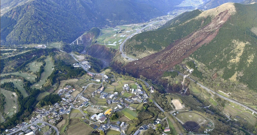
  • 在海洋中的人工岛上建造机场(如日本的神户机场)。

1. 适用于土壤复杂性质和各种应用环境的技术

  土壤是一种复杂的材料,包括密实度不同的矿物骨架mineral skeleton)和分布其间的孔隙,空气和水能在孔隙中自由流动。土壤颗粒有些由岩石破碎形成,如大小各异的卵石、砾石、砂砾或粉砂;也有些来源于某些岩石的化学风化,这一过程会形成微小的粘土颗粒。水分很容易在渗水性土壤(例如卵石、砾石和砂砾)中流动,但在低渗透性或甚至不透水的土壤(例如粉砂和黏质土)中,情况则大不相同:水在黏土中的流动速率是在砾石中的一百万分之一。此外,受水分入渗、干旱或地震等外部应力的作用,土壤的机械物理性质可能会发生变化,变得不再适合其设计用途。

  由于土壤和建筑物结构的类型各有不同,因此有必要选择适合土壤性质及其环境的土壤加固方案。迄今为止,如何找到合适的方案依然是个十分复杂的问题,这一点在现存的历史遗迹上也得到了证明(例如比萨斜塔)。目前主要采用两种技术提高土壤的机械物理性能:改变土壤的内部结构和向土壤中添加筋材(inclusions)进行加固。土壤机械物理性能改良技术能提高土壤的密实度,具体而言包括降低孔隙度的固化consolidation)技术,如对水分饱和的土壤施加过载压力,在土壤沉降过程中逐渐排出水分;或者对土壤施加振动作用,重新排列土壤颗粒,提高其密实度(如强夯技术dynamic compaction technique〕,将15至150公吨的物体从20至40米的高空坠落,其冲击力可能使10米深度内的土壤紧实致密)。土壤加固技术包括向土壤中加入垂直或水平的加固单元。所有这些技术都致力于确保建筑物不出现过度形变或失稳。

环境百科全书-土壤加固-土壤原味加固
图1. 土壤原位加固。
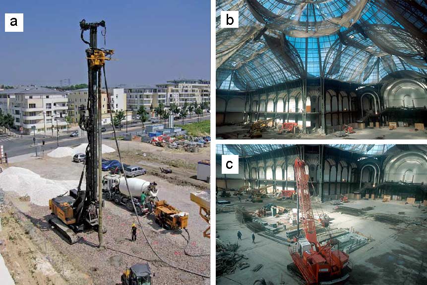
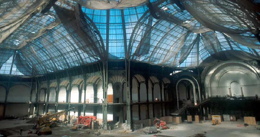
(a) 刚性加筋 [图片来源:凯勒照片集], (b)和(c) 巴黎大皇宫地基的加固 [图片来源:索莱坦什·巴希照片集]。

2. 多样化解决方案

  常用的土壤加固技术有如下两种:一是向土体中垂直楔入筋材,这些筋材或部分露出地表,或全部隐藏于地下(图1);二是采用水平配筋(条状、板状、或蜂窝状结构等)以及或短或长的纤维去重塑和加固土体,建造挡土墙(图2)。

2.1. 土壤原位加固

环境百科全书-土壤加固-通过支撑结构加固土壤
图2. 通过支撑结构加固土壤。
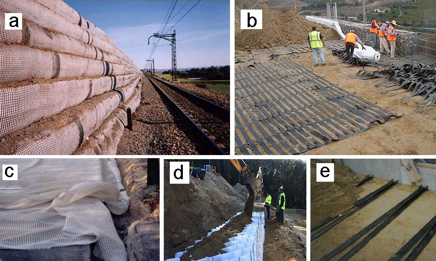
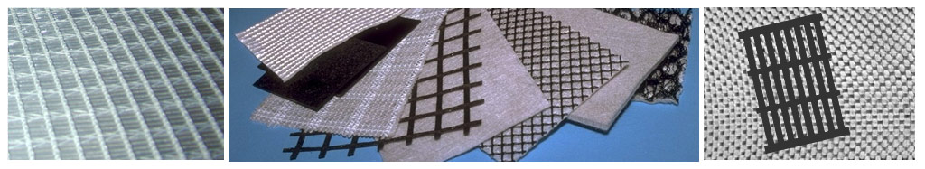
(a) 土工合成材料加固墙; (b) 土工格栅加固; (c) 土工织物网加固; (d) 蜂窝结构加固(图片来源:阿玛特工艺(Armater process)[1])和 (e) 土工布加固。

  最古老的土壤原位加固技术是采用木桩将建筑物的荷载分配或传递至更大面积或更抗压的土壤。在法国的贝奈斯村(安德尔-卢瓦尔省)附近挖掘出了一条可追溯至公元前8年罗马时期的道路遗迹,该道路穿过一座潮湿的山谷,长度超过200 m,路基由约30 cm厚的“石质台阶”(硅质石块)砌成。顺着路基两侧铺设石块,石块间有深深埋入沙质土壤中的石桩。目前还有残留木桩共27根,其中一些仍然与石块紧密相连。这些橡木桩平均长1 m,直径30 cm。为便于砸入,木桩下端都削成了倾面。在这里,还发现了3组排列密集的木桩,每组由相距1.60至1.70 m的两根木桩构成,这表明当时已经产生了使用刚性竖向构件加固的创新做法。将刚性竖向筋材等间距插入地下,上部与一层石块连接,通过石块重新分配施加到路面的荷载,一部分落在竖向构件的顶部,另一部分则分布到竖向筋材之间的土壤中。这一实例正是目前所有加筋土结构的应用原则:都包括一个规则分布的刚性竖向植筋网络和一个水平的颗粒层荷载分配结构。

环境百科全书-土壤加固-刚性加筋系统
图3. 悬浮式和锚定式刚性加筋系统。
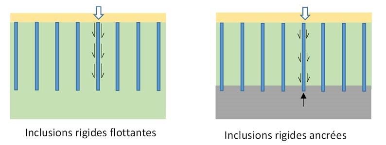
(inclusions rigides flottantes悬浮式刚性加筋;inclusions rigides ancrees锚定式刚性加筋)

  根据压缩土壤的不同厚度,桩的长度和作用也不同。当土层性能较差、厚度较薄时,可以将桩的底部锚定到稳定的土层中,这样桩顶部的受力可通过桩直接传递到下部的稳定层(桩锚);而当土层性能较差、厚度较厚时,可楔入足够长的桩,通过桩与土壤间的摩擦力分散建筑物施加在桩头的全部载荷(图3)。

  进一步改善上述基本方法后,形成了旨在大幅降低表土沉降的新技术,例如:

  • 刚性混凝土加筋,向土壤中钻孔(通过旋转或振动作用)直达支撑土层,在钻具抽出的同时使混凝土在重力作用下从下部注入孔中;
  • 铺碴,无疑是最灵活的方法,将无黏性的颗粒状材料铺置地表,经由后续车辆通行进行压实;
  • 喷射灌浆柱,在钻孔中通过高压射流使土体高度破碎化,将破碎后的土壤与自硬化浆液混合,在土壤中形成柱状筋条;
  • 混合土柱,在土体中将土壤与粘合剂(干柱)或浆液(湿柱)原位混合,搅拌形成圆形立柱。
环境百科全书-土壤加固-刚性加筋的原理
图4. 刚性加筋的工作原理。
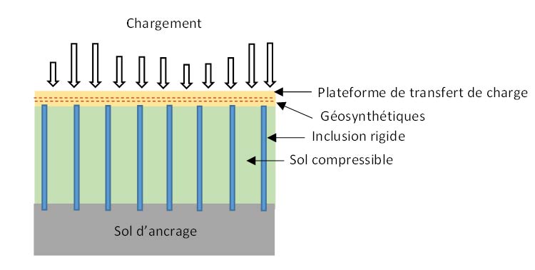
(chargement 载荷;plateforme de transfert de charge 负载转移平台;géosynthétiques土工合成材料;inclusion rigide刚性筋材;sol compressible压缩土;sol d’ancrage锚定地层)

  刚性植筋由于良好的经济性和易操作性而成为了应用最广泛的加固技术,它可以通过增加颗粒垫层或在建筑物下设置加筋垫层以提高加固效果。该技术可以将传递至压缩土壤的垂直载荷限制在合理范围内,通过荷载传递机制将建筑物的垂直荷载引导至立桩,同时最大限度减少可能影响桩群稳固性的水平荷载分量(图4)。

  从环境保护的角度来看,这些解决方案引人入胜,因为不需要在原地挖掘土壤,减少了材料运输过程中的环境污染和移动受污染土壤的风险。土工合成材料〔土木工程中使用的塑料、透水性(土工织物或相关产品)或不透水性(土工膜)等合成材料〕可发挥不同的功能:隔离、保护、加固、排水、过滤、密封、抗侵蚀等。在铺碴加固工程中使用这些材料,可以降低石碴层的厚度,减少对“昂贵”材料的需求。

2.2. 土方回填加固

  将土壤与添加物混合或土壤与添加物交替成层以加固填方,这种方式早已投入使用。早在公元前2100年,美索不达米亚地区花费大量人力、物力建造金字形神塔时,就添加了稻草编织物来加固建筑。在乌鲁克建造的第一座金字形神塔是后续几十年来该地区所有台阶式塔建筑的原型,其中保存最完好的是乌尔塔庙(距今3000年)。此后加固技术发生了许多变化,更演变出了新的加固方式。

环境百科全书-土壤加固-土工合成材料
图5. 一些土工合成材料。

  1957年的某个海滨沙滩上,法国土壤加固公司(Terre Armée)[2]创始人亨利·维达尔(Henri Vidal)表示:当你踏上一堆沙子时,沙堆会坍塌,沙粒向四面八方散开;但如果往沙子里插入几排松针,即使你施加很大的力,整个结构仍旧保持稳定。亨利·维达尔落实了该理念,发展出建造挡土墙的新型加固技术,后来进一步演变成多种技术形式,如:

  • 等间距水平放置金属平板(加筋)或合成材料进行加固。
  • 土工合成材料层加固(图5)。
环境百科全书-土壤加固-挡土墙的演变
图6. 挡土墙的演变。
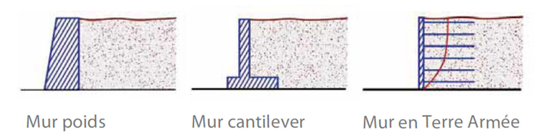
(mur poids 重力墙;mur cantilever悬臂墙;mur en terre armée Terre Armée墙)

  这两种样式在垂直立面都没有支撑结构,而垂直立面具有防侵蚀功能。值得注意的是,这两种样式的基础结构稳定性都由对抗土体变形的筋材来保证,通过筋材与土壤间的摩擦力实现加固。这种支撑本身在设计上极具创新,因为加固土体能确保其自身的稳定性,无需建造阻止土体移动的挡土墙——重力墙或悬臂墙。悬臂墙是一种钢筋混凝土支撑墙,由桩基和墙体组成。与传统挡土墙相比,悬臂墙的优势在于桩基后部的浇筑板有助于提升其自身稳定性(图6)。

环境百科全书-土壤加固-技术使用环境
图7. (a) 滑坡体的稳定 [图片来源:休斯克图片集];
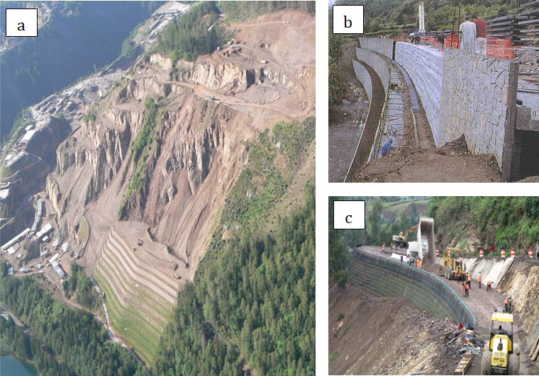
(b) 刚性立面挡土墙; (c) 柔性立面挡土墙 [图片来源:休斯克图片集]。

  这些技术之所以被广泛使用,是因为它们占地面积小,并且适用于崎岖不平和地势险要的地区(图7)。其模块化的构造使之和谐融入当地景观,部分外露表面可借助植被覆盖,几乎难以觉察挡土墙的存在。

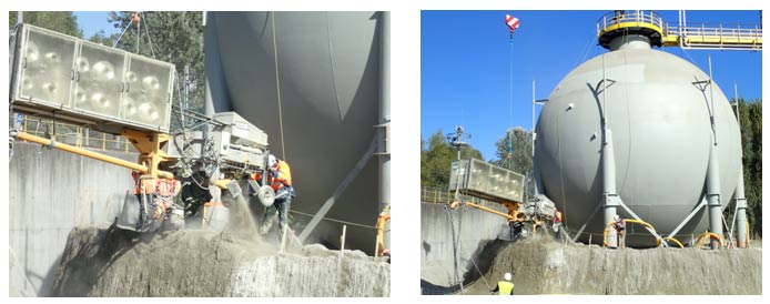
  此外,有时也会采用添加短或长纤维的方法加固土体,但是应用极少(图8)。使用时将纤维与土壤均匀混合,起到局部加固的作用。另外,由于土壤/纤维混合物能消散能量,还可将该技术用于降低气罐爆炸后可能的损害。再者,纤维与土壤颗粒之间的摩擦、长纤维拉固土壤颗粒等,都是加固作用的基础。

3. 复杂的作用机制

环境百科全书-土壤加固-沙质山地中的气罐
图8. 用长纤维加固技术保护位于沙质山地中的气罐-特索尔工艺(Texsol process)[3]。 [图片来源:J.P.古尔克]

  实际上,这些加固技术利用了土壤和加强筋之间复杂的相互作用机制,需通过分析或数值计算进行建模,以模拟某些简化的假设。值得一提的是,土壤与加强筋之间的界面区域是将土壤应力传递给加强筋的首要媒介,如果这个界面绝对光滑,就无法传递应力,即加固效果为零。

  怎么理解这个界面interface)呢?界面的厚度为零或者仅有几个土壤颗粒的厚度,土壤的应力通过界面传递至加强筋。要使摩擦力最大化,界面处加强筋和土壤之间必须产生显著的相对位移(根据加强筋的不同材料,至少需要几毫米,甚至几厘米的位移)。界面的粗糙程度也能影响可传递力的大小。通常采用被称为库仑摩擦角的物理量来表征界面性质。交替式荷载(交替出现相对正位移与负位移)下应力的强度和方向不断变化,因而很难预测发生周期性荷载变化(如风作用于风力发电机、汽车或火车反复通行、周期性的冰冻/解冻、土壤膨胀/收缩等)时的加固效果。

  那么筋材inclusions)呢?虽然其作用显而易见,即加固土壤,但是其作用方式有时候很复杂,不同情形下可谓天差地别。土工合成纤维和合成布主要承受拉力(无压缩或弯曲力)。有一定弯曲刚度的土工格栅筋材会同时承受拉力和弯曲力(垂直于土工格栅平面的力)。桩型的竖向加筋主要通过压缩力起作用,只有少数工艺允许存在水平作用力。

  至于土壤,其性质随时间可能发生复杂变化。例如,在桩筋网格中存在一种称之为“穹顶效应(vault effect)”的机制,将负荷从薄弱地基转移到抵抗力更强的地区。

4. 先进技术仍在发展

  优化这些技术和降低生产成本仍然是一个挑战,需要全世界的研究人员参与。最新的技术、新的加固材料、不断变化的气候和土壤条件都是不得不重新考量的新因素。幸运的是,调查能力也在进步,尤其是在调查规模方面。虽然传统工程的计算方法已获得广泛的测试和验证,但在复杂的情况下,工程人员更频繁地使用先进的数值模型。计算机性能呈指数级增长,如今我们得以完成几年前不可能实现的计算。

  经典的工程计算方法是将土壤作为连续体,采用有限元法或有限差分法,利用数值法求解微分方程和偏微分方程。将研究环境划分为不同的场域(由节点元构成的网格),分别求解问题方程。网格尺寸、元的种类和模型的选择决定了解的准确性。这些方法可以把每个筋材、以及每个筋材与土壤的界面都考虑进去,并设置相关土壤性质的取值范围,得到与实际相当吻合的计算结果。

环境百科全书-土壤加固-模拟模型
图9. 模拟负载传递机制连续(左)和离散(右)模型,在桩筋阵列上方有一个颗粒层。
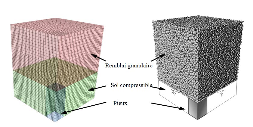
(remblai granulaire粒状填料;sol compressible压缩土;pieux 桩)

  我们是否可以梦想建立一个数字模型,将每一个土壤颗粒和筋材都纳入考虑?答案是肯定的,事实上已经有人在尝试这一模型,由接触动力学或分子动力学发展出的离散数字方法discrete digital method)便是其基础。把要研究的环境切分为一组不同形状的独立颗粒,它们在接触点上相互作用,其行为符合牛顿第二定律。这类相互作用通常只需要很少的描述参数,并且可以应用于多种研究领域。与连续模型不同,这类模型非常适合研究中介质发生强形变、开裂和断裂。利用这类模型,可以考虑每一颗土壤颗粒的形状及其与筋材间的相互作用,用很少的参数实现对土壤和筋材行为的有效模拟。这类模型对于理解土壤与筋材界面以及土壤内部微域的作用机制非常有潜力,因而在研究中得以广泛应用。但复杂的技术原理和难以承受的计算时间成本导致其目前很少用于建筑或者局部建筑工程的模拟计算。未来几十年内,计算时间或将不再是一个障碍。

  那么实验人员呢?随着仪器技术和传感器的不断发展,他们的重要性也在下降。如今,获得过去难以想象的数据量已不再是难事,可以更好地了解加固的机理。目前,正在使用先进的仪器对小型或集中式实验室模型和全尺寸工程进行广泛研究。

5. 监测加固工程

  加固工程技术复杂,必须进行长期监测,特别是当其引起严重经济和环境挑战的情况下。可以在工程设计阶段就加入仪表自控,以便在施工建造时控制工程状态并验证其尺寸是否与设计相符;在某些情况下,仪表自控可用来优化建筑工程尺寸,即工程测量的观察方法。基于仪表自控、结构健康监测SHM,Structural Health Monitoring)技术和岩土工程结构的设计和维护,可以预测岩土结构的损坏情况,防止事故的发生。在统计处理系统的支持下,结构健康监测还可以延长工程的使用年限,降低维护成本。除了检查程序以外,该方法还可以在加固工程使用期内自动对其进行有计划的监测。得益于市场上出现的新一代传感器(特别是光纤测量)以及汇集于自动数据采集中心的先进通信和测量传输手段,结构健康监测技术正在快速发展。

6. 未来会怎样?

  众所周知,人类生来就有征服欲,他们会在一切可能的地方定居,特别是在公认难以进行工程施工的地区,如海床上。随着对环境的关注日益增加,我们将使用更经济、更生态友好的新技术。为此,研究人员正在开发数值模拟和实验之间的耦合方法,以深入理解土壤性质和土壤-筋材界面,从而优化土壤加固解决方案。随着岩土检测技术的发展,上文提到的观察法也会有新的用武之地。最后,人类可能会利用细菌等意想不到的新盟友,例如,我们已经使用细菌来提高地基的承载能力(生物钙化技术)和清除污染。土壤加固前途一片光明!


参考资料及说明

[1] Armater: http://enka-solutions.com/en/home/

[2] Armed Land: http://www.terre-armee.fr/TA/wtaf_fr.nsf

[3] Texsol: http://www.eiffageinfrastructures.com/home/produits/texsol.html


The Encyclopedia of the Environment by the Association des Encyclopédies de l'Environnement et de l'Énergie (www.a3e.fr), contractually linked to the University of Grenoble Alpes and Grenoble INP, and sponsored by the French Academy of Sciences.

To cite this article: VILLARD Pascal, BRIANÇON Laurent (March 12, 2024), 土壤加固:必不可少的技术, Encyclopedia of the Environment, Accessed July 27, 2024 [online ISSN 2555-0950] url : https://www.encyclopedie-environnement.org/zh/sol-zh/soil-reinforcement-techniques-become-essential/.

The articles in the Encyclopedia of the Environment are made available under the terms of the Creative Commons BY-NC-SA license, which authorizes reproduction subject to: citing the source, not making commercial use of them, sharing identical initial conditions, reproducing at each reuse or distribution the mention of this Creative Commons BY-NC-SA license.