


Underground storage of gas and hydrocarbons: prospects for the energy transition
PDF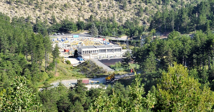
The hiker who crosses the magnificent landscapes of the Luberon on the Manosque side can, after crossing a herd of sheep and his shepherd, walk along industrial installations discreetly inserted between two hills: some offices, pumping stations, well heads (Figure 1). He will not suspect that he has under his feet, at a depth of one kilometre, a significant part of the French strategic oil reserve: nearly 10 million tonnes, almost two months of consumption, spread over some forty caves several hundred metres high dug in a layer of salt. We will then see what challenges this technique addresses and what the costs, risks and opportunities are.
1. Why store hydrocarbons?
Hydrocarbons (oil and natural gas) still account for more than half of French energy consumption. Almost all of these hydrocarbons are imported: 77 Mtoe (million tonnes of oil equivalent) of oil and 34.4 Mtoe of natural gas in 2015 [1]. A supply interruption, such as the one in 1973 following the so-called Kippur war, would have disastrous consequences. The State therefore requires oil and gas companies to have two to three months’ reserves. In the case of oil, a large part of the storage is carried out in Manosque (Cover image). In the case of natural gas, in addition to the strategic concern, there is another concern: one-third of consumption is used for heating, so demand varies considerably between summer and winter.
The production system – in the oil fields – and the transport system – by pipeline or LNG tanker – require considerable investment. Adjusting it so that it can instantly meet the peak demand of the coldest days of the year would be an economic absurdity: a large part of the investments would be perfectly useless the rest of the year. It is better suited to build on (or rather under) national soil easily mobilizable reserves that will make it possible to “smooth” peaks in demand. For natural gas, most of the storage is carried out underground. Such reserves exist in all industrial countries: a Strategic Petroleum Reserve of 700 million barrels (100 million tons) of crude oil is established in Texas and Louisiana, in salt cavities, which can be mobilized upon signature by the President of the United States.
The energy transition will not make these techniques obsolete. Intermittent production of electricity from wind or photovoltaic sources will require large storage capacities. The basement offers great opportunities. The techniques envisaged are most often inspired by those already used to store hydrocarbons
2. Hydrocarbon storage techniques
2.1. Storage in an aquifer layer

- a sufficient thickness (at least several tens of metres)
- high values of the average porosity ϕ (volume proportion of voids that gas can occupy in the rock) and the average permeability K (it determines the ease with which fluids flow), ϕ = 20% and K = 10-12 m2, ideally.
- a cover (Figure 2, Zone 1) of sufficient thickness, very low permeability and high inlet pressure (i.e. the excess pressure of the gas over the pressure of the water contained in the pores of the cover material necessary to overcome capillary forces and enter the cover). For the gas “bubble”, lighter than water, to be trapped, the cover must be curved in shape; it must be free of fractures that could conduct fluids.
- a horizontal surface under the convex part of the sufficient coverage; it determines the extension of the gas bubble (S = 5 km2 is satisfactory).

The pressure of the injected gas must be higher than the pressure of the water to be moved in the tank (Figure 2, zone 2). It must be lower than the pressure that would allow gas to enter the cover (Figure 2, Zone 1). The maximum gradient at the top of the tank is defined as the maximum gas pressure divided by the depth. It is fixed site by site; it does not exceed 0.015 MPa/m (the natural gradient of water in the reservoir is about 0.01 MPa/m). If a height h = 20 m is used in the reservoir, the volume occupied by the gas at the bottom is V = Shϕ = 5 km2 x 20 m x 20% = 20 million m3. If this gas is at depth H = 500 m and the pressure gradient at the top of the tank is γ = 0.012 MPa/m, the gas pressure is γH = 6 MPa (60 bar). It therefore occupies a volume 60 times smaller than if it were at atmospheric pressure (Pv = rT): on the ground surface, the volume of stored gas would therefore be 20 million m3 x 60 = 1.2 billion m3 and its mass is, by definition, 1.2 billion Nm3 (the Nm3, or Normal m3, is the mass of one m3 of gas at ordinary temperature and pressure, 1 Nm3 = 0.68 kg). The annual consumption of natural gas in France is 35 billion Nm3 and the 13 French storage facilities in aquifers or depleted reservoirs allow 11 billion Nm3 to be stored.
Storage is implemented gradually: in the first year gas is stored during the summer, part of it is extracted the following winter, then a larger quantity is stored the following summer until the final stock is reached after about 20 years for example. The horizontal extension of the gas “bubble” increases. The injection-drafting wells (Figure 2, Zone 4) are therefore dug as needed, until several dozen wells are reached in the final configuration. A portion of the stored gas, about 50%, penetrates into very small pores from which it can no longer be removed (“cushion gas”). This gas is lost, but only once: as the years go by, it represents only a small fraction of the total gas that has passed through storage.
The stored gas must remain contained. The initial recognition makes it possible to verify the favourable geometric and hydrogeological conditions and the progressive digging of the wells makes it possible to confirm them, by sampling samples and logistic measurements (one goes down into a well, at the end of a cable, a sensor which measures the gas and water content, porosity, temperature etc). On the periphery of the gas bubble, there are holes (Figure 2, zone 5) in which the water pressure is monitored. It is not so much the arrival of gas in a borehole that we are trying to detect (the number of boreholes is small compared to the size of the area to be monitored) as the consistency of the pressure data collected. To this end, from the outset, a hydrogeological model of the reservoir is built; the history of the injected and withdrawn flows and the pressure measurements carried out continuously on the wells make it possible to improve it gradually by comparing forecasts and measurements (history matching).
The monitoring system generally includes a well (Figure 2, Zone 6) that stops in a sufficiently permeable aquifer layer above the reservoir (Figure 2, Zone 7). As in peripheral boreholes, water pressure is measured to detect a possible leak of gas that would accumulate in this upper aquifer, known as the “control” aquifer.
The preservation of the quality of the groundwater used for storage is a key concern. The injected gas is cleaned and the presence of heavy elements or benzene is carefully monitored. The gas bubble increases the pressure of the water table and can modify its hydrodynamics. Agreements often bind all parties involved in the conservation and exploitation of the groundwater to share the information collected in order to ensure optimal management of the groundwater.
2.2. Storage in an uncoated gallery
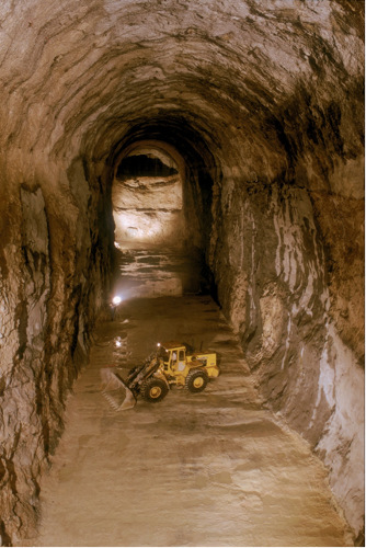
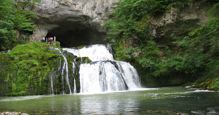
The galleries are connected to the surface by a vertical shaft, filled with water and closed at the bottom with a thick concrete plug through which the tubes used for fluid circulation pass. Figure 4 illustrates the excavation of an 18 m high gallery in Lavéra (Bouches-du-Rhône) in chalk. The massif is permeable. The products are confined by maintaining their pressure below the pressure of the water in the massif at the depth of the structure, so that the water permanently enters the gallery, preventing reverse movement. This is called “dynamic” sealing. But this mine water reduces the volume available for the products and could increase the pressure until the direction of flow is reversed. It must therefore be pumped continuously.
In France, products (propane or butane) are stored in a biphasic state (liquid and gas in equilibrium), as in a lighter, which offers additional safety: a decrease in the available volume causes condensation of the gas phase and not an increase in pressure. In the biphasic state, the pressure of propane at 15°C is 0.8 MPa, i.e. a pressure of 80 metres of water: the gallery must be placed at a greater depth, typically 130 m, to have a margin while limiting the flow of mine water, which increases with the depth of the structure under the water table.
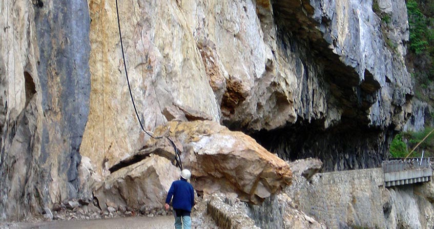
These hydraulic conditions must be maintained at all times. For example, a block fall from the roof of the cavity would raise the highest point of the gallery and the margin against a reversal of the flow direction would be reduced. For this reason, a careful geotechnical study leading to possible reinforcements is essential before filling the storage area. The pressure of the products is in principle constant, by construction, but care must be taken to avoid volatile fractions (ethane, methane) contained in the stored fluid that can accumulate in the top of the cave and gradually modify the pressure.
Similarly, the condition at the upper limit (the depth of the free surface of the slick) must be maintained, taking into account possible episodes of drought, or also the fall of the slick that will be caused by the flow towards the gallery. Ideally, the massif should be not very permeable in the immediate vicinity of the structure – so that the water flow to the structure is moderate – but much more permeable above – to ensure a satisfactory recharge. If natural conditions are not sufficient, this can be remedied by creating a “water curtain” consisting of a small gallery above the structure from which radiant soundings can be drawn. A constant water pressure is maintained. Monitoring includes a network of piezometers to measure the pressure of water in the groundwater. There are eight such galleries in France, divided into three sites.
2.3. Storage in salt cavities
There are very large masses of salt (NaCl) below the soil surface. In France, the surface area they occupy is around 20,000 km2, with thicknesses that can reach one kilometre. Large underground cavities can be created by dissolution (Figure 4). An oil well is dug until the salt formation. It is equipped with a metallic casing, cemented to the ground, which isolates it from the ground it passes through. A second tube, of smaller diameter, like a straw in a bottle, is then introduced into it; it allows fresh water to be injected into the saline formation. The water dissolves the salt and the brine produced is passed up through the annular space between the two metal tubes. The brine produced must be disposed of by discharging it into the sea or by supplying it to a chemical plant that consumes NaCl.
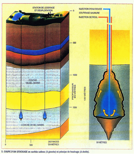
When storing liquid or liquefied products, the central tube used for leaching is left in the cave. The stored products are less dense than brine and “float” above it. When brine is injected through the central tube, products are extracted through the annular space and vice versa. Therefore, a brine tank should be provided on the surface of the soil. The pressure of the fluids in the cave, which is in the order of ybz where yb = 0.012 MPa/m is the volume weight of the brine, varies little over time.
When storing natural gas, the cave is first emptied of brine. The operation is that of a gas cylinder: the pressure varies due to the stock, PV = mrT; the (absolute) temperature T and the volume V of the cave vary little, and the pressure P of the gas is approximately proportional to the mass of gas stored m. However, extreme values are set. The maximum gradient at the low end (“hoof”) of the casing is typically 0.018 MPa/m, to provide a margin against fracturing (see The challenges of industrial hydraulic fracturing).
The minimum pressure is often set by considerations of cave stability. Indeed, salt, although solid, behaves in the long term like an extremely viscous fluid (it “flows”) and cavities tend to close. The closing speed can reach a few % per year when the caves are deep (1300 m and above) and the gas pressure is low. This closure causes the surface land to descend. However, this remains moderate (a few tens of cm), due to the low diameter/depth ratio. Thus, among the approximately 2000 storage caverns existing in the world, there is no known case of land collapse that is linked to a saline storage cavity. There are about 80 salt storage cavities in France, spread over six sites: Tersanne and Le Grand Serre in the Drôme, Etrez and Viriat in the Ain, Manosque gas and liquid Manosque in the Alpes-de-Haute-Provence.
3. The cost

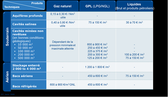
Table 1, provided by the French company Geostock, gives an order of magnitude of the costs of underground storage. In general, it is much lower than the cost of overhead storage (i.e. on the ground surface). In the case of salt cavities, the price per m3 of vacuum (30 to 70 euros) is only a fraction of the price of the product (the price per barrel of oil – about 160 litres – is around $50 in 2017, but was rather $100 a few years ago, so 300 to 600 euros per m3). Mined cavities are more expensive, but the cost decreases quickly with the size of the cavities. The cost of building aquifer storage is in the order of 0.15 to 30 euros per “useful” m3, i.e. the m3 that can actually be extracted if necessary, excluding the “cushion”.
4. The risks
Evans [2] has shown that, throughout the entire chain of production, storage and distribution of petroleum products, underground storage is the least accident-prone link. There are simple reasons for this[3]: at depth, in the absence of oxygen from the air, products cannot explode or burn; they are protected by several hundred metres of land from external attacks, tornadoes, fires, plane crashes, attacks; and they are not very sensitive to earthquakes, whose maximum effect is most often on the ground. They are economical in terms of the area occupied on the ground surface (Cover image).
In the case of gaseous or liquefied hydrocarbons, the rupture of the wellhead could lead to a complete emptying. In Europe, natural gas wells (cavity or aquifer) are equipped with an underground safety valve that is automatically activated in the event of a wellhead failure.
The most frequent accident is a defect in the metal casing or its cementation that allows the products to travel to the surface through the ground, as in the recent accident in Aliso Canyon, California. In France, natural gas storage requires the presence of a second metal tube that forms an annular space with the cemented casing, closed at the bottom, which is filled with water. A leakage initiation is thus detected immediately at the surface.
Prevention/monitoring also includes leak tests which, in the USA, are carried out periodically throughout the life of the storage. In the case of salt cavities, these tests consist in filling the annular space in the well with a fluid that is difficult to mix with brine (fuel oil or nitrogen) and checking over several days that its mass remains constant by measuring the depth of the interface. This test, mandatory in the USA, is very accurate.
5. Abandonment of storage facilities
Experience has shown that mine abandonment can raise difficult problems later on in terms of surface land stability and the return to a balanced groundwater regime. For hydrocarbon storage, an experiment is available: the storage of fuel oil in the May-sur-Orne mine and propane storage in Carresse (in a salt cavity), Vexin (gallery in chalk) and Petit-Couronne (gallery in chalk) have been abandoned.
The first problem is to clear the walls of hydrocarbon residues. Access structures (wells and boreholes) must be carefully closed. For storage in aquifers, it is necessary to analyse the very long-term behaviour of the cushion gas left in the structure. The abandoned salt cavities will be filled with brine and the future of the large bodies of salt water left in the subsoil must be examined. French companies and academics, very active in this field, have shown that a balance is established in which the pressure of the brine in the cave remains lower than the fracturing pressure (see The challenges of industrial hydraulic fracturing).
6. The future of underground storage
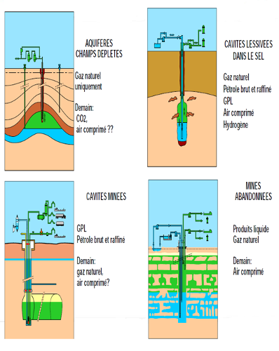
France is well equipped with underground hydrocarbon storage facilities. The techniques thus available could be applied to the storage of other energy products and resources to make a decisive contribution to the energy transition [4], either by limiting the amount of greenhouse gases released into the atmosphere or by offering flexibility downstream of intermittent renewable electricity production (solar, wind turbines) – a problem that is not always sufficiently measured. The most commonly considered applications are as follows.
CO2 sequestration consists in collecting it from large producers (cement works, steel industry) and injecting it into a saline aquifer (in order not to burden drinking water resources). This technique has a certain analogy with natural gas storage in aquifers, from which it seems appropriate to draw inspiration (geometric recognition, double casing, safety valve, history matching). However, there are differences: CO2 can be stored in a supercritical state – i.e. in a dense form. It can dissolve in large quantities in water. In addition, CO2 is likely to remain confined for longer periods than the peak of global warming, ten centuries to set ideas, which raises the question of the monitoring to be carried out during such periods. Finally, the masses of CO2 to be injected are much larger than those contained in natural gas storage. For example, at one of the 3 main CO2 injection sites in Sleipner, Norway, 16.5 million tonnes were injected, more than all natural gas storage facilities in France (around 10 million tonnes). However, this site alone has only a small impact in terms of limiting atmospheric emissions of greenhouse gases. Projects have not been able to resist the low carbon price that discourages investment, but this unfavourable environment could change.
Hydrogen storage (H2). Hydrogen, produced by electrolysis of water, is an efficient means of storing electricity periodically produced in excess by intermittent energies. Hydrogen can be injected into the natural gas network (up to 10%); it can be used for methanation or as a fuel. Hydrogen is already stored in the salt cavity in Texas and Great Britain, typically for hydrocarbon desulphurization, so that the means for mass storage will be immediately available when the time comes.
The storage of methane produced from CO2. Methanation is the formation of methane (CH4) from hydrogen H2, obtained by electrolysis, combined for example with CO2 produced after combustion of methane at the end of the cycle. It may also involve the storage of O2 and CO2. Salt cavities also offer a solution and some new problems, for example thermodynamic, since the stored CO2 can dissolve in large quantities in the small quantity of brine inevitably left at the bottom of the cavern.
Compressed air storage. There are two sites in the salt cavity, in Germany and the USA. Excess electricity is used to compress air, which is injected at night and then extracted during the day to power a turbine. The efficiency is about 50%, especially because the compressed gas must be cooled before it is injected into the cavern. To improve it, it is planned to store (rather on the surface) the heat recovered at the compression outlet. However, the mechanical energy stored per m3 of cavity is not significant compared to the chemical energy stored in 1 m3 of natural gas cavity. The success of hydrocarbons is not due to chance!
This form of storage creates interesting mechanical problems. In case of rapid withdrawal, the expansion produces an intense cooling of the gas, especially when approaching adiabatic behaviour, for example in a very large cave. At the wall, the salt contracts and additional tensile stresses appear, to which the rock is not very resistant: fractures can open in the cooled area. These effects have been widely studied. It seems that the micro-fractured area remains limited to a thin “skin” on the wall of the caves.
France has long had the means to store 25% of its annual natural gas consumption underground and, in the case of liquid hydrocarbons, around 10%. French companies operate and build underground storage facilities all over the world. The energy transition is inevitable, even if the paths it will follow are difficult to predict. It will require large energy storage capacities. The technical know-how accumulated with the storage of hydrocarbons is an asset for future developments.
References and notes
Cover image. Surface installations for crude oil storage in a salt cavity near Manosque, Alpes-de-Haute-Provence[storage of liquid hydrocarbons; Source: © Photothèque Géostock]
[1] Source: Key energy figures. Edition 2017. Ministry of Environment, Energy and the Sea in charge of international climate relations. Observation and Statistics Department. February 2017
[2] Evans, D.J. 2009. A review of underground fuel storage problems and putting risk into perspective with other areas of the energy supply chain. In Evans D. J. & Chadwick, R. A. (eds) Underground gas storage: worldwide experiences and future development in the UK and Europe. Geological Society of London Special Publication, 313, 173-216.
[3] Bérest P., Brouard B. 2003. Safety of salt caverns used for underground storage. Oil & Gas Science and Technology Journal – Rev. IFP, Vol. 58, 3:361-384.
[4] Ineris. Underground storage in the context of the energy transition. Ineris references, September 2016.
Acknowledgements. The author would like to thank Eric Chaudan (Storengy) and Arnaud Réveillère (Géostock) and LP for their suggestions.
The Encyclopedia of the Environment by the Association des Encyclopédies de l'Environnement et de l'Énergie (www.a3e.fr), contractually linked to the University of Grenoble Alpes and Grenoble INP, and sponsored by the French Academy of Sciences.
To cite this article: BEREST Pierre (February 16, 2021), Underground storage of gas and hydrocarbons: prospects for the energy transition, Encyclopedia of the Environment, Accessed July 27, 2024 [online ISSN 2555-0950] url : https://www.encyclopedie-environnement.org/en/soil/underground-storage-gas-and-hydrocarbons-prospects-for-energy-transition/.
The articles in the Encyclopedia of the Environment are made available under the terms of the Creative Commons BY-NC-SA license, which authorizes reproduction subject to: citing the source, not making commercial use of them, sharing identical initial conditions, reproducing at each reuse or distribution the mention of this Creative Commons BY-NC-SA license.